Categories
PDF

shoe rack plans pdf

Discover a world of organized footwear! Free PDF shoe rack plans empower you to build stylish, functional storage, transforming cluttered spaces into havens of order.

Why Build Your Own Shoe Rack?

Embrace the satisfaction of crafting a personalized storage solution! Building your own shoe rack, guided by readily available PDF plans, offers significant advantages. You gain complete control over dimensions, style, and materials, ensuring a perfect fit for your space and aesthetic preferences.

Furthermore, DIY construction is often more cost-effective than purchasing pre-made options. Free plans, easily downloadable, unlock a world of design possibilities, from simple wooden racks to industrial pipe creations and even bench-integrated storage. It’s a rewarding project boosting home organization and showcasing your craftsmanship!

Benefits of Using PDF Plans

PDF plans streamline your DIY shoe rack project, offering clear, concise instructions and visual diagrams; These downloadable resources eliminate guesswork, providing precise measurements and cutting lists for efficient material usage. They often include detailed assembly guides, ensuring a smooth construction process, even for beginners.

Accessibility is key – plans are readily available online from various websites like MyMyDIY and Pinterest. Scaling plans to your desired size is straightforward, and understanding symbols simplifies interpretation. PDFs are easily printable, allowing for convenient on-site reference during building!

Types of Shoe Rack Plans

Explore diverse designs! PDF plans offer options ranging from simple wooden racks and industrial pipe styles to floating shelves and bench-integrated storage solutions.

Simple Wooden Shoe Rack Plans

For beginners, simple wooden shoe rack plans are readily available as free PDF downloads. These typically involve basic cuts and assembly, utilizing readily accessible lumber like pine or plywood. Many plans focus on creating tiered shelving, maximizing vertical space for efficient shoe storage.

Expect straightforward diagrams and material lists, perfect for honing fundamental woodworking skills. Scrap wood projects are also popular, offering a cost-effective and eco-friendly approach. These plans often prioritize functionality over elaborate aesthetics, resulting in a durable and practical storage solution.

Industrial Pipe Shoe Rack Plans

Embrace an urban aesthetic with industrial pipe shoe rack plans, frequently found as downloadable PDF guides. These designs utilize black iron pipes and fittings, combined with wooden shelves for a robust and stylish storage solution. Plans detail pipe cutting, threading (if necessary), and assembly techniques.

Expect a more involved build than simple wooden racks, requiring basic plumbing knowledge or a willingness to learn. The resulting rack offers a unique, durable, and visually striking addition to mudrooms, entryways, or closets. Many plans offer customizable height and width options.

Floating Shoe Shelf Plans

Maximize floor space with sleek floating shoe shelf plans, readily available as PDF downloads. These plans typically involve constructing individual shelves supported by hidden brackets securely anchored to the wall. Designs range from single-tier displays to multi-level storage systems, catering to diverse shoe collections.

Consider wall stud locations for optimal support and weight distribution. Plans will specify bracket types, shelf dimensions, and mounting instructions. Floating shelves offer a minimalist aesthetic, ideal for modern interiors, and provide easy access to frequently worn shoes.

Bench with Shoe Storage Plans

Combine seating and storage with practical bench and shoe storage plans, often found as downloadable PDF guides. These plans typically feature a comfortable bench seat atop a base incorporating shelves or cubbies specifically designed for shoes. They’re perfect for entryways or mudrooms.

Explore designs ranging from simple, rustic benches to more elaborate builds with cushioned seats and decorative details. Plans detail lumber requirements, cutting lists, and assembly steps, ensuring a functional and stylish addition to your home.

Cabinet Style Shoe Rack Plans

Elevate your entryway with sophisticated cabinet-style shoe rack plans, readily available as PDF downloads. These plans offer a concealed storage solution, keeping shoes neatly hidden behind doors or stylish facades. Designs vary from compact single-door cabinets to larger, multi-tiered units.

Detailed PDF guides provide precise measurements, material lists, and step-by-step instructions for constructing a durable and aesthetically pleasing cabinet. Many plans incorporate adjustable shelves to accommodate various shoe heights and styles.

Materials Needed for Construction

Essential supplies include wood (pine, plywood), fasteners like screws and nails, and finishing touches – paint, stain, or varnish – as detailed in PDF plans.

Wood Options (Pine, Plywood, etc.)

Selecting the right wood is crucial for a durable and aesthetically pleasing shoe rack. Pine is a cost-effective and easily workable option, ideal for painted finishes. Plywood offers excellent stability and strength, particularly useful for shelves and larger structures, though edges may require finishing.

Hardwoods like oak or maple provide superior durability and a beautiful grain, but come at a higher price point. Consider the PDF plans’ recommendations, as they often specify suitable wood types based on the design’s structural needs and intended aesthetic. Scrap wood can also be repurposed for smaller projects!

Fasteners (Screws, Nails, Glue)

Secure assembly relies on appropriate fasteners. Screws offer superior holding power compared to nails, especially for plywood and hardwoods, and are recommended by most shoe rack plans PDF guides. Wood glue, used in conjunction with screws, creates incredibly strong and lasting joints.

Nails are suitable for softer woods like pine, but pre-drilling is advised to prevent splitting. Ensure screw lengths are appropriate for the wood thickness to avoid breakthrough. Always refer to the PDF plan’s fastener specifications for optimal results!

Finishing Materials (Paint, Stain, Varnish)

Enhance your DIY shoe rack with a protective and aesthetically pleasing finish! Paint provides vibrant color options and seals the wood, while stain highlights the natural grain. Many shoe rack plans PDF suggest applying a primer before painting for better adhesion and coverage.

Varnish offers durable protection against scratches and moisture, ideal for high-traffic areas. Consider water-based options for low odor and easy cleanup. Always follow the PDF plan’s recommendations for specific finish types and application techniques.

Tools Required for the Project

Successful DIY shoe rack builds depend on having the right tools! PDF plans often detail essential hand and power tools for efficient construction.

Essential Hand Tools

Embarking on a DIY shoe rack project necessitates a core set of hand tools for precision and control. A reliable measuring tape is paramount for accurate cuts, guided by the dimensions detailed in your PDF plans. A quality hand saw, though potentially slower than power tools, offers finesse for intricate cuts.

Essential also are a sturdy screwdriver set – both Phillips and flathead – for assembling the frame and securing shelves. A hammer proves invaluable for driving nails, if your chosen plan incorporates them. Don’t overlook the importance of a square to ensure right angles, guaranteeing a structurally sound and aesthetically pleasing final product. Sandpaper, in various grits, will smooth rough edges and prepare surfaces for finishing.

Power Tools for Efficiency

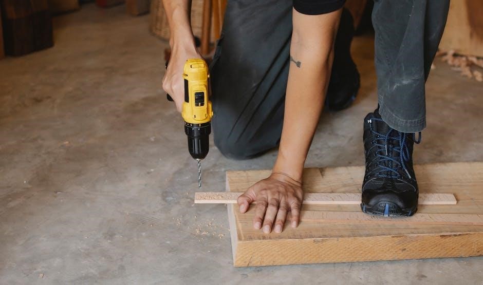
To accelerate your DIY shoe rack build, consider incorporating power tools. A circular saw dramatically speeds up cutting wood pieces according to your PDF plans, ensuring consistent and straight lines. An electric drill/driver simplifies screw insertion, saving time and effort compared to manual screwdrivers.

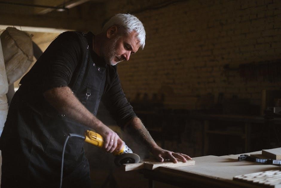
A power sander efficiently smooths surfaces, preparing them for finishing. For more complex designs, a jigsaw can handle curved cuts. Remember safety – always wear appropriate protection when operating power tools, and consult your plan for specific tool recommendations.

Safety Equipment

Prioritizing safety is paramount when executing your shoe rack plans. Always wear safety glasses to protect your eyes from flying debris during cutting and sanding. A dust mask prevents inhalation of wood particles, crucial for respiratory health. Ear protection, like earmuffs, minimizes noise exposure from power tools.

Work gloves enhance grip and shield hands from splinters. Sturdy footwear provides stability. When using power tools, ensure a clear workspace and understand the tool’s operation before starting – referencing your PDF plan is key!

Step-by-Step Construction Guide (General)

Follow your PDF plan closely! Cut wood accurately, assemble the frame securely, and then add shelves – ensuring stability throughout each construction phase.

Cutting the Wood Pieces

Precise cuts are paramount for a successful shoe rack build! Your PDF plans will detail each piece’s dimensions; transfer these measurements carefully onto your chosen wood. Utilize a saw – hand or power – ensuring straight, clean lines. Double-check measurements before each cut to minimize errors and wood waste.

Remember safety glasses and appropriate ear protection. Consider using a speed square as a guide for accurate 90-degree angles. Label each piece immediately after cutting, referencing your plan, to avoid confusion during assembly. A well-executed cut list sets the foundation for a sturdy and aesthetically pleasing final product.

Assembling the Frame

With your wood pieces accurately cut, it’s time to construct the shoe rack’s frame! Refer closely to your PDF plans for guidance on joinery – screws, nails, or wood glue are common. Begin by connecting the side pieces to the base, ensuring square corners. Clamps are invaluable here, holding pieces firmly while fasteners set.

Pre-drilling pilot holes prevents wood splitting, especially with hardwoods. Regularly check for squareness using a carpenter’s square. A solid, well-aligned frame is crucial for the rack’s stability and overall appearance. Proceed slowly and methodically for optimal results.

Adding Shelves or Racks

Now, bring your shoe rack to life by installing the shelves or rack supports! Your PDF plans will detail the precise placement and attachment method. Depending on the design, this might involve screwing shelves directly into the frame, using shelf pins for adjustability, or constructing angled racks.

Ensure shelves are level and securely fastened to prevent shoes from sliding off. Consider the height needed for different shoe types – boots require more space. Reinforce larger shelves with additional supports for increased durability and weight capacity.

Finding Free Shoe Rack Plans (PDF)

Unlock a treasure trove of free PDF shoe rack plans online! Websites like MyMyDIY and Pinterest offer diverse designs for every skill level.

Popular Websites Offering Free Plans

Numerous online platforms generously provide downloadable PDF shoe rack plans, catering to various tastes and construction abilities. MyMyDIY stands out, boasting a curated collection of 24 savvy DIY projects with free blueprints, ranging from simple scrap wood cabinets to industrial pipe designs. Pinterest serves as a vibrant inspiration hub, linking to countless plans and tutorials shared by DIY enthusiasts.

Exploring these resources reveals options like easy mudroom benches with integrated shoe storage and floating bench designs featuring convenient shoe shelves. Remember to carefully review plan details before commencing your build!

Pinterest Inspiration & Links

Pinterest is a treasure trove of shoe rack plans PDF, visually showcasing diverse designs and linking directly to project tutorials. A quick search reveals 18+ people actively seeking inspiration, with consistently updated ideas. Expect to find plans for everything from minimalist floating shelves to elaborate cabinet-style organizers.

Many pins lead to detailed blog posts and downloadable PDFs, offering step-by-step instructions. Explore boards dedicated to DIY furniture and home organization to uncover hidden gems and customize plans to perfectly fit your space and style preferences.

MyMyDIY Resources

MyMyDIY presents a curated collection of 24 savvy DIY shoe rack plans, all available as free blueprints. These resources cater to various skill levels, from beginner-friendly scrap wood projects to more ambitious industrial pipe designs. Expect detailed guides and clear instructions to facilitate successful builds.

The site emphasizes inspiring projects, offering a diverse range of storage solutions – including mudroom benches with integrated shoe storage and sleek floating shelves. Explore their offerings to find the perfect plan to declutter your entryway!

Advanced Shoe Rack Designs

Elevate your storage! Explore rotating racks, hidden solutions, and sophisticated cabinets with doors – detailed shoe rack plans for the discerning builder.

Shoe Cabinet with Doors

Craft a refined entryway with a shoe cabinet! PDF plans offer detailed instructions for building a cabinet that conceals footwear, creating a tidy appearance. These plans typically include dimensions for various shoe sizes and configurations, ensuring ample storage.

Consider incorporating adjustable shelves to accommodate boots or taller shoes. Door styles range from simple shaker to more ornate designs, allowing for customization. Many free and premium shoe rack plans online showcase different cabinet builds, offering inspiration for your project. Prioritize sturdy hinges and smooth-closing mechanisms for lasting quality.

Rotating Shoe Rack Plans

Maximize space with a rotating shoe rack! PDF plans for these innovative designs allow easy access to all your shoes without bending or reaching. These plans often feature a central rotating base and tiered shelves, optimizing vertical storage.

Construction typically involves plywood or solid wood, requiring accurate cuts and sturdy assembly. Look for plans detailing bearing mechanisms for smooth rotation. While more complex than basic racks, the convenience of a rotating design is invaluable. Explore online resources for shoe rack plans offering varying levels of difficulty.

Hidden Shoe Storage Solutions

Declutter your entryway with ingenious hidden shoe storage! PDF plans reveal designs seamlessly integrated into benches, walls, or even under-stair spaces. These solutions prioritize discretion, concealing footwear while maintaining a tidy aesthetic.

Plans often involve building custom cabinetry or modifying existing furniture. Consider pull-out drawers, tilting compartments, or concealed shelving. Successful implementation requires precise measurements and careful construction. Search for shoe rack plans emphasizing space-saving and aesthetic integration for a truly organized and stylish home.

Customization Options

PDF plans are a springboard! Adjust dimensions, add decorative flourishes, or blend materials – personalize your shoe rack to perfectly complement your home’s style.

Adjusting Dimensions to Fit Your Space

PDF plans offer fantastic flexibility! Don’t be constrained by preset sizes; easily modify dimensions to suit your specific needs and available space. Scaling tools within PDF viewers allow precise adjustments to length, width, and height.

Consider your shoe collection’s size and the intended location – hallway, bedroom, or entryway. Carefully recalculate material lists after scaling to ensure accurate purchasing. Remember to maintain structural integrity when altering dimensions; larger racks may require additional support.

This customization ensures a perfect fit, maximizing storage without overwhelming your area.

Adding Decorative Elements

Elevate your DIY shoe rack beyond mere functionality! PDF plans provide a solid base, but personalization is key. Incorporate decorative touches to complement your home’s style. Consider painting, staining, or applying stencils for a unique finish.

Add molding, trim, or even repurposed materials for visual interest. Woven baskets within the shelves offer concealed storage and texture. A cushioned top transforms the rack into a bench.

Let your creativity shine – these details transform a practical item into a beautiful statement piece!

Incorporating Different Materials

Expand beyond traditional wood! PDF shoe rack plans can inspire combinations with diverse materials. Industrial designs thrive with metal pipes and reclaimed wood, offering a robust aesthetic.

Woven rope or fabric panels add texture and a coastal vibe. Consider using durable plastics for moisture-prone areas like mudrooms.

Blending materials creates visual appeal and enhances functionality. Don’t be afraid to experiment – a touch of creativity can transform a simple rack into a unique, eye-catching piece!

Downloading and Using PDF Plans

Access detailed shoe rack plans in PDF format! Understand symbols, scale accurately, and troubleshoot common issues for a smooth, successful build.

Understanding Plan Symbols and Diagrams

Decoding PDF shoe rack plans begins with recognizing common symbols. Lines indicate cuts, arrows show joining directions, and dimensions are crucial for accuracy. Diagrams visually represent the finished product and assembly steps. Pay close attention to wood grain direction indicated on plans; this impacts strength and appearance.

Symbols for screws, nails, and glue types will also be present. Familiarize yourself with these before starting. Understanding these visual cues ensures correct interpretation and minimizes errors during construction, leading to a sturdy and aesthetically pleasing shoe rack;

Scaling Plans for Accurate Cuts

Ensuring precise cuts starts with correctly scaling your PDF shoe rack plans. Most plans aren’t full-size; a scale ratio (e.g., 1:2 or 1:4) will be indicated. Use a ruler to verify the scale on a test line before printing or transferring measurements.

If printing, confirm your printer settings don’t automatically adjust the scale. For manual transfer, utilize a grid system to accurately enlarge dimensions. Accurate scaling prevents misaligned pieces and structural weaknesses, guaranteeing a professional-looking final product.

Troubleshooting Common Issues

Decoding PDF shoe rack plans can present challenges. Missing dimensions or unclear diagrams are frequent hurdles. Cross-reference with similar plans online or consult woodworking forums for clarification. If wood pieces don’t align, double-check your cuts against the scaled plan – errors often stem from inaccurate measurements.

Stripped screws? Pre-drill pilot holes! Wobbling structure? Reinforce joints with wood glue and clamps. Don’t hesitate to adapt the plan if needed, prioritizing stability and functionality.

Shoe Rack Maintenance and Care

Protect your handcrafted shoe rack! Regular cleaning and wood protection—paint, stain, or varnish—ensure lasting beauty and structural integrity for years to come.

Cleaning and Protecting the Wood

Maintaining your DIY shoe rack’s wood finish is crucial for longevity. Dust regularly with a soft cloth to prevent buildup. For deeper cleaning, use a wood-specific cleaner, always testing in an inconspicuous area first. Avoid harsh chemicals or abrasive materials that could damage the finish.

Protecting the wood involves reapplying varnish, stain, or paint as needed, typically every 1-2 years, depending on wear. This shields against moisture, scratches, and UV damage. Consider a protective sealant for added durability, especially in high-traffic areas. Proper care ensures your creation remains beautiful and functional.

Repairing Minor Damage

Addressing small scratches or dents promptly prevents them from worsening. For minor scratches, gently rub with a furniture touch-up marker matching the wood’s color. Deeper scratches may require wood filler, sanded smooth once dry, and then refinished to blend seamlessly.

Loose joints can be re-secured with wood glue and clamps. If screws become stripped, replace them with slightly larger ones. Regularly inspect your shoe rack for any signs of wear and tear, tackling repairs early to maintain its structural integrity and aesthetic appeal.

Categories
PDF

ipc 620b pdf

IPC-A-620B PDF: A Comprehensive Article Plan

The IPC-A-620B PDF document details materials, methods, and tests for cable/wire harness assemblies. It establishes acceptability criteria for crimped, mechanically secured, and soldered interconnections, ensuring quality and reliability.

This standard is crucial for industries relying on consistent, high-quality wiring.

IPC-A-620B represents a cornerstone in the realm of electronic assembly, specifically focusing on the meticulous requirements for cable and wire harness assemblies. This widely adopted standard, available as a PDF document, isn’t merely a set of guidelines; it’s a comprehensive framework designed to ensure consistent quality, reliability, and performance in these critical components.

Developed collaboratively by IPC and the Wire Harness Manufacturers Association (WHMA), IPC-A-620B addresses the entire lifecycle of cable and harness production, from material selection to final inspection. It’s a vital resource for manufacturers, inspectors, and anyone involved in the creation or evaluation of these assemblies.

The standard’s significance stems from its detailed specifications for crimped, mechanically secured, and soldered interconnections. It provides clear acceptability criteria, enabling objective assessment of workmanship and adherence to industry best practices. Utilizing IPC-A-620B minimizes defects, reduces rework, and ultimately enhances the dependability of electronic products across diverse applications.

Understanding and implementing IPC-A-620B is not just about compliance; it’s about building a reputation for excellence and delivering products that meet the highest standards of quality and safety.

What is IPC-A-620B?

IPC-A-620B is a globally recognized standard – readily accessible as a PDF – detailing requirements for the assembly of cable and wire harness assemblies. Officially titled “Requirements and Acceptance for Cable and Wire Harness Assemblies,” it’s published jointly by IPC and WHMA (Wire Harness Manufacturers Association). It’s not a prescriptive ‘how-to’ guide, but rather a specification defining what constitutes acceptable quality.

The standard meticulously covers materials, methods, and testing procedures. It defines acceptability criteria for various interconnection techniques, including crimping, mechanical securing, and soldering. This ensures a consistent benchmark for evaluating the quality of workmanship and the reliability of the finished product.

Essentially, IPC-A-620B provides a common language and set of expectations for manufacturers and their customers. It facilitates clear communication, reduces ambiguity, and minimizes disputes regarding quality control. The PDF version allows for easy distribution and reference throughout the production process.

Adherence to IPC-A-620B demonstrates a commitment to industry best practices and a dedication to delivering high-quality, dependable cable and wire harness assemblies.

Purpose and Scope of the Standard

The primary purpose of the IPC-A-620B standard – available as a comprehensive PDF document – is to establish a uniform, internationally recognized set of requirements for producing high-quality cable and wire harness assemblies. It aims to minimize defects, enhance reliability, and ensure consistent performance across diverse applications.

The scope of IPC-A-620B is remarkably broad. It encompasses all phases of assembly, from material selection to final inspection. Specifically, it details acceptable practices for crimped, mechanically secured, and soldered interconnections. The standard doesn’t dictate specific tooling or processes, but defines the results that must be achieved.

This PDF specification covers a wide range of wire types, terminal configurations, and assembly techniques. It provides detailed guidance on inspection criteria, including visual checks and functional testing. It’s applicable to both manual and automated assembly processes.

Ultimately, IPC-A-620B serves as a vital tool for manufacturers, inspectors, and end-users, promoting quality, reducing costs, and fostering confidence in the integrity of cable and wire harness assemblies.

Key Areas Covered by IPC-A-620B

The IPC-A-620B PDF standard meticulously details several key areas crucial for producing reliable cable and wire harness assemblies. A significant focus is on crimped interconnections, outlining acceptable crimp heights, pull-force requirements, and visual inspection criteria. It also extensively covers soldered interconnection requirements, specifying solder joint quality, wetting, and potential defects.

Mechanical securing techniques, such as tie-wrapping, potting, and strain relief, are thoroughly addressed, ensuring long-term durability and protection against environmental factors. The standard also provides detailed guidance on cable and wire harness assembly details, including wire routing, bundling, and labeling practices.

Furthermore, IPC-A-620B dedicates substantial attention to testing and inspection procedures, defining acceptable defect levels and outlining methods for verifying conformance to the standard. This includes visual inspection, electrical testing, and mechanical pull testing.

Finally, the PDF document clarifies conformance determination and limits, providing a clear framework for assessing whether an assembly meets the required quality standards.

Target Industries and Applications

The IPC-A-620B PDF standard serves a diverse range of industries where reliable cable and wire harness assemblies are paramount. The aerospace industry heavily utilizes it, ensuring the safety and performance of critical avionics systems. Similarly, the automotive sector relies on IPC-A-620B to guarantee the dependability of wiring harnesses in vehicles.

Medical device manufacturers employ this standard to maintain the integrity of life-sustaining equipment, where failure is not an option. Industrial automation benefits from IPC-A-620B, ensuring robust connections in control systems and machinery. Consumer electronics, including computers and appliances, also leverage the standard for quality control.

Furthermore, the military and defense industries depend on IPC-A-620B for the production of ruggedized and dependable wiring systems. Telecommunications infrastructure, power supplies, and various other electronic applications all benefit from adhering to the guidelines outlined in the PDF document. Essentially, any industry requiring dependable wired connections finds value in this standard.

Understanding the IPC-A-620B Document Structure

The IPC-A-620B PDF document is meticulously structured to provide comprehensive guidance on cable and wire harness assembly. It begins with a foreword outlining the standard’s purpose and scope, followed by sections detailing materials, methods, and acceptance criteria. The document is organized logically, progressing from general principles to specific interconnection techniques.

Key sections cover crimped interconnections, soldered connections, and mechanical securing methods, each with detailed requirements and illustrations. Appendices provide supplementary information, including definitions, glossaries, and examples. The PDF format allows for easy navigation and searching, enabling users to quickly locate relevant information.

Throughout the document, clear language and visual aids enhance understanding. Tables and figures illustrate acceptable and unacceptable conditions, aiding in inspection and quality control. The structure facilitates consistent application of the standard across different manufacturing environments. Understanding this structure is vital for effective implementation of IPC-A-620B guidelines.

Sections of the Standard: Overview

The IPC-A-620B PDF standard is divided into distinct sections, each addressing a critical aspect of cable and wire harness assembly. Initial sections define scope, purpose, and applicable terminology. Subsequent sections detail requirements for crimped terminations, covering wire preparation, connector selection, and crimping process controls.

A significant portion focuses on soldered interconnections, outlining acceptable solder joint characteristics, flux usage, and cleaning procedures. Mechanical securing techniques, including tie-wrapping, potting, and strain relief, are also thoroughly addressed. Dedicated sections cover wire and cable preparation, including stripping, tinning, and marking.

Furthermore, the standard includes sections on inspection criteria, acceptance testing, and documentation requirements. Appendices provide valuable supplementary information, such as material specifications and troubleshooting guides. The PDF document’s organization allows users to efficiently navigate to specific areas of interest, ensuring comprehensive coverage of all relevant assembly processes.

Acceptability Criteria: A Detailed Look

The IPC-A-620B PDF standard establishes stringent acceptability criteria for all cable and wire harness assemblies. These criteria are categorized based on the class of application – typically Class 1 (general electronic products), Class 2 (dedicated service electronic products), and Class 3 (high-performance/continuous reliability). Each class dictates different levels of acceptance for defects.

For crimped interconnections, criteria address terminal crimp height, pull-force resistance, and wire insulation displacement. Solder joint acceptability focuses on wetting, coverage, and the absence of defects like shorts or opens. Mechanical securing techniques are evaluated based on proper application, securement strength, and prevention of wire damage.

The PDF document details visual inspection guidelines, specifying acceptable and unacceptable conditions for each type of interconnection. It also outlines procedures for performing functional testing to verify electrical performance. Conformance is determined by comparing the assembly to these defined limits, ensuring consistent quality and reliability.

Materials Covered by the Specification

The IPC-A-620B PDF specification comprehensively covers a wide range of materials utilized in cable and wire harness assemblies. This includes various wire types – stranded, solid, and multi-conductor cables – specifying insulation materials like PVC, Teflon, and polyethylene. Connector materials, encompassing metals like brass, tin, and gold plating, are also detailed, alongside requirements for their composition and finish.

Soldering materials, including solder alloys (tin-lead, lead-free) and fluxes, are addressed, outlining acceptable compositions and application methods. Crimping tools and terminals are also within the scope, with specifications for material hardness and dimensional accuracy. The PDF document also covers materials used for mechanical securing, such as cable ties, clamps, and potting compounds.

Furthermore, the standard references acceptable materials for labeling and marking, ensuring durability and legibility. It’s crucial that all materials used conform to the IPC-A-620B requirements to guarantee a reliable and compliant assembly.

Methods for Crimped Interconnections

The IPC-A-620B PDF dedicates significant detail to methods for achieving reliable crimped interconnections. It outlines proper terminal and wire strip length requirements, crucial for ensuring sufficient contact area and preventing stress on the connection. The standard specifies acceptable crimping tool types – including ratchet, automatic, and pneumatic – and emphasizes the importance of tool calibration and maintenance.

Detailed guidance is provided on crimp profile dimensions, including crimp height, width, and angle, all vital for establishing a gas-tight seal and mechanical strength. The PDF document also addresses insulation displacement connectors (IDCs), detailing proper insertion techniques and acceptable damage limits. Pull-test requirements are clearly defined, specifying the force needed to separate a properly crimped connection.

Furthermore, the standard covers techniques for repairing damaged crimps and emphasizes the importance of visual inspection for defects like cracked insulation or incomplete crimps. Adherence to these methods, as detailed in the IPC-A-620B, is paramount for producing durable and dependable crimped connections.

Soldered Interconnection Requirements

The IPC-A-620B PDF provides comprehensive requirements for soldered interconnections within cable and wire harness assemblies. It details acceptable solder alloys, emphasizing the importance of selecting materials compatible with the conductors and terminals being joined. Specific guidance is given regarding flux types, application methods, and cleaning procedures to prevent corrosion and ensure long-term reliability.

The standard meticulously defines acceptable solder joint characteristics, including fillet size, wetting, and the absence of defects like voids, bridging, or insufficient solder. Detailed visual acceptance criteria are provided, illustrated with clear examples of acceptable and unacceptable joints. Temperature profiles for soldering processes, including wave soldering and hand soldering, are also addressed.

Furthermore, the IPC-A-620B outlines requirements for through-hole and surface mount soldering, considering variations in component density and thermal mass. Repair procedures for solder joints are also covered, emphasizing proper techniques for removing and replacing defective components. Strict adherence to these guidelines, as outlined in the PDF, is essential for producing high-quality, dependable soldered connections.

Mechanical Securing Techniques

The IPC-A-620B PDF dedicates significant attention to mechanical securing techniques for wires and cables, offering detailed guidance beyond soldering and crimping. This section covers a range of methods, including tie-wrapping, lacing, potting, and the use of clamps and supports. The standard emphasizes the importance of strain relief to prevent damage to conductors and connections due to vibration or movement.

Specific requirements are outlined for tie-wrap tension, ensuring sufficient support without causing conductor deformation or insulation damage. Lacing techniques are detailed, specifying appropriate materials and patterns for secure and organized wire management. The IPC-A-620B also addresses the selection and application of potting compounds, focusing on material compatibility and complete encapsulation.

Furthermore, the PDF document provides guidance on the proper use of clamps and supports, ensuring they are appropriately sized and positioned to prevent chafing or stress on the wires. Visual acceptance criteria are defined for each technique, allowing for consistent inspection and verification of conformance. Adhering to these mechanical securing requirements, as detailed in the IPC-A-620B, is vital for long-term reliability and performance.

Testing and Inspection Procedures

The IPC-A-620B PDF outlines comprehensive testing and inspection procedures crucial for verifying cable and wire harness assembly quality. These procedures are designed to ensure conformance to the standard’s acceptability criteria, covering visual, mechanical, and electrical tests. Visual inspection, a cornerstone of the process, focuses on identifying defects like improper crimps, solder voids, and damaged insulation, as detailed within the PDF.

Mechanical testing, as described in the document, includes pull tests to verify connection strength and bend tests to assess wire flexibility and resistance to damage. Electrical tests, such as continuity and insulation resistance measurements, confirm circuit integrity and prevent short circuits. The IPC-A-620B specifies sampling plans and acceptance levels, guiding inspectors on the number of assemblies to test and the allowable number of defects.

Detailed instructions within the PDF cover test equipment calibration, test setup, and data recording. Proper documentation of test results is emphasized for traceability and quality control. Consistent application of these testing and inspection procedures, as outlined in the IPC-A-620B, is essential for delivering reliable and high-performance wire harness assemblies.

Conformance Determination and Limits

Determining conformance to the IPC-A-620B PDF standard relies on meticulously comparing manufactured assemblies against the specified acceptability criteria and limits. The PDF document details these limits for various interconnection types – crimped, soldered, and mechanically secured – defining acceptable defect levels. These limits are categorized by class, reflecting the intended application’s severity (Class 1, 2, and 3).

The IPC-A-620B employs a sampling plan approach, outlined within the PDF, to assess large production runs efficiently. These plans specify the number of samples to inspect and the allowable number of defects based on lot size and quality level. The document clearly defines defect types – critical, major, and minor – each with associated severity and acceptable limits.

Failure to meet the specified limits results in non-conformance, requiring corrective action. The PDF emphasizes the importance of documented evidence demonstrating conformance, including test reports and inspection records. Understanding and adhering to these conformance determination rules and limits, as detailed in the IPC-A-620B, is vital for ensuring product reliability and customer satisfaction.

Cable and Wire Harness Assembly Details

The IPC-A-620B PDF provides extensive details regarding cable and wire harness assembly, covering a broad spectrum of requirements. It addresses wire preparation, including stripping, tinning, and splicing techniques, ensuring reliable electrical connections. The PDF specifies requirements for conductor insulation, shielding, and jacketing materials, impacting performance and durability.

Detailed guidance is offered on harnessing construction, encompassing bundling, lacing, and securing methods. The standard dictates appropriate materials and techniques for strain relief, protecting connections from stress and vibration. Furthermore, the IPC-A-620B outlines requirements for labeling and marking, ensuring traceability and proper identification.

The PDF also delves into connectorization practices, specifying proper mating and securing methods. It addresses issues like wire-to-wire, wire-to-board, and board-to-board connections. Adhering to these detailed assembly guidelines, as presented in the IPC-A-620B, is crucial for producing high-quality, reliable cable and wire harness assemblies that meet industry standards.

IPC-A-620B Training and Certification

IPC-A-620B PDF documentation highlights the importance of proper training and certification for personnel involved in cable and wire harness assembly. The IPC/WHMA-A-620B standard supports a comprehensive Training and Certification Program designed to ensure consistent application of the standard’s requirements.

This program equips individuals with the knowledge and skills necessary to accurately interpret and implement the IPC-A-620B guidelines. Training covers acceptability criteria, materials, methods, and testing procedures detailed within the PDF. Successful completion of the program demonstrates competency in producing high-quality assemblies.

Becoming a Certified IPC Trainer (CIT), as referenced in available resources, allows individuals to deliver authorized IPC-A-620B training. The CIT designation signifies expertise and the ability to effectively disseminate knowledge of the standard. Certification validates adherence to industry best practices, ultimately enhancing product reliability and reducing defects. Accessing approved training programs is vital for maintaining compliance and achieving optimal results.

CIT (Certified IPC Trainer) Designation

The IPC-A-620B PDF standard’s supporting documentation emphasizes the value of the Certified IPC Trainer (CIT) designation. This certification signifies an individual’s qualification to deliver authorized training on the IPC/WHMA-A-620B standard, ensuring consistent and accurate knowledge transfer.

Achieving CIT status requires successful completion of a rigorous training program and demonstration of a thorough understanding of the IPC-A-620B requirements. CITs are authorized to utilize the designation on professional materials, including letterhead and business cards, signifying their expertise to clients and colleagues.

The CIT program ensures that training aligns with the latest revisions of the IPC-A-620B PDF, maintaining the relevance and accuracy of the information presented. This is crucial for organizations seeking to implement or maintain compliance with the standard. A qualified CIT can effectively educate personnel on acceptability criteria, inspection methods, and best practices for cable and wire harness assembly, ultimately improving product quality and reliability.

Accessing the IPC-A-620B PDF Document

The IPC-A-620B PDF document isn’t typically available for free direct download. Instead, access is generally facilitated through the IPC (Association Connecting Electronics Industries) website or authorized distributors. Users often need to purchase a license to view and utilize the complete standard.

The IPC offers various purchasing options, including single-user licenses and enterprise-wide access, catering to different organizational needs. These licenses grant access to the official PDF version, ensuring users have the most current and accurate information. Be cautious of unofficial sources offering free downloads, as these may contain outdated or inaccurate content.

Furthermore, some organizations may have internal access to the IPC-A-620B PDF through corporate subscriptions. Checking with your company’s engineering or quality assurance departments is advisable. Accessing the official document is crucial for ensuring compliance and understanding the detailed requirements outlined within the standard, covering everything from materials to inspection procedures.

Updates and Revisions: IPC-A-620B vs. Previous Versions

IPC-A-620B represented a significant update from earlier versions, primarily focusing on clarifying and expanding acceptability criteria for modern wiring harness assemblies. Previous iterations, while foundational, lacked the detailed guidance needed for increasingly complex interconnect technologies.

Key changes in IPC-A-620B included enhanced sections on crimped interconnections, reflecting advancements in connector designs and tooling. The standard also provided more comprehensive coverage of mechanical securing techniques and soldering requirements, addressing evolving industry practices. Updates were made to testing and inspection procedures, emphasizing the importance of consistent quality control.

The revision aimed to align with current manufacturing capabilities and address emerging challenges in cable and wire harness assembly. While older versions served as valuable references, IPC-A-620B offered a more robust and detailed framework for ensuring product reliability and conformance. Staying current with the latest revisions is vital for maintaining industry best practices and meeting customer expectations.

Resources and Further Information

For accessing the IPC-A-620B PDF document and related resources, the official IPC website (www.ipc.org) is the primary source. Here, you can purchase the standard directly and find details about updates and revisions. Additionally, the WHMA (Wiring Harness Manufacturers Association) website (www.whma.org) provides valuable supplementary information.

IPC offers comprehensive training and certification programs related to IPC-A-620B. These programs, delivered by Certified IPC Trainers (CITs), equip professionals with the knowledge and skills to implement the standard effectively. A directory of CITs is available on the IPC website, allowing you to locate training opportunities near you.

Numerous online resources, including industry forums and technical articles, offer insights into IPC-A-620B application. Remember to verify the credibility of information from non-official sources. Regularly checking the IPC and WHMA websites ensures you have the most current and accurate information regarding this critical standard for cable and wire harness assembly.

Categories
Manuals

biddeford electric blanket manual

Biddeford Electric Blanket Manual: A Comprehensive Guide

This manual provides essential guidance for Biddeford electric blanket owners‚ covering safety‚ operation‚ and maintenance. It details crucial recall information from October 22‚ 2022‚ impacting approximately 394‚000 units‚ alongside details about the CPSC’s involvement.

Understanding Your Biddeford Electric Blanket

Biddeford electric blankets offer comforting warmth‚ but understanding their features is key to safe and effective use. These blankets utilize integrated wiring and heating elements to provide adjustable heat levels. The Biddeford Textile Corporation prints the blankets model name and serial number on a label‚ typically located near the control switch connection point – this information is vital for identifying potential recall participation.

Familiarize yourself with the blanket’s construction; understanding the materials used contributes to proper care. The control switch‚ a central component‚ governs temperature and timer settings. Knowing these settings‚ including the auto-off feature‚ ensures personalized comfort and energy conservation. Proper identification of your specific model is crucial‚ especially considering the October 2022 recall affecting a significant number of units.

Safety Precautions & Warnings

Prioritize safety when using your Biddeford electric blanket. Never use a damaged blanket or one with a frayed cord. Avoid folding the blanket excessively‚ as this can damage the internal wiring. Do not use pins‚ clips‚ or other objects that could puncture the fabric and compromise safety.

Crucially‚ be aware of the October 22‚ 2022 recall impacting 394‚000 units in cooperation with the U.S. Consumer Product Safety Commission (CPSC); Check your model number against the recalled list. Never use the blanket while wet. Disconnect the blanket from the power source before washing or storing. Individuals with sensitivities or medical conditions should consult a physician before use. Improper use can pose a fire or burn hazard; always follow the manual’s guidelines.

Identifying Your Blanket Model & Serial Number

Locating your Biddeford blanket’s model and serial number is vital‚ especially concerning the October 22‚ 2022 recall affecting 394‚000 units. This information is crucial for determining if your blanket is subject to the CPSC safety notice.

The model name and serial number are printed on a label. This label is typically found in close proximity to where the control switch plugs into the blanket itself. Carefully inspect this area. Record both the model name and the serial number for future reference‚ particularly if contacting Biddeford Textile Corp. regarding the recall or for warranty purposes. Accurate identification ensures you receive the correct support and information related to your specific blanket.

Locating the Control Switch

The control switch for your Biddeford electric blanket is essential for operation and safety. Its location varies slightly depending on the blanket model‚ but it’s consistently designed for easy access during use.

Typically‚ the control switch is found along one of the edges of the blanket. Look for a small‚ rectangular or square box attached to the fabric. This switch allows you to adjust temperature settings and activate the timer or auto-off features. Remember that the blanket’s model and serial number label are usually located near where the control switch plugs into the blanket. Familiarize yourself with its position before use‚ and always ensure a secure connection.

Understanding Control Settings

Your Biddeford electric blanket’s control switch offers several settings for personalized comfort and safety. These typically include multiple temperature levels‚ a timer function‚ and an auto-off feature‚ all designed for convenient operation.

The control settings allow you to customize the warmth to your preference. Lower settings provide gentle warmth‚ while higher settings deliver more intense heat. The timer function lets you pre-set the blanket to turn off after a specific duration‚ conserving energy and enhancing safety. Furthermore‚ the auto-off feature automatically shuts off the blanket after a set period‚ preventing overheating and ensuring peace of mind. Understanding these settings is key to maximizing your blanket’s benefits.

Temperature Settings Explained

Biddeford electric blankets generally feature multiple heat settings‚ often numbered or indicated with symbols. Lower numbers or symbols (like ‘1’ or a single bar) represent the lowest heat level‚ providing gentle warmth ideal for maintaining comfort without overheating.

Medium settings (like ‘2’ or two bars) offer a balanced level of warmth‚ suitable for most users. Higher settings (like ‘3’ or three bars) deliver the maximum heat output‚ best for quickly warming up or for individuals who prefer intense warmth. It’s recommended to start with a lower setting and gradually increase it until you reach your desired comfort level. Always avoid using the highest setting for extended periods to prevent discomfort or potential safety concerns.

Timer Functionality

Many Biddeford electric blankets incorporate a timer function‚ allowing you to pre-set the duration of operation. This feature enhances safety and energy efficiency by automatically turning the blanket off after a specified period. Typical timer settings range from 30 minutes to 10 hours‚ offering flexibility to suit individual needs.

To utilize the timer‚ press the timer button repeatedly to cycle through the available options until your desired duration is displayed. The blanket will then operate for the selected time before automatically shutting off. Using the timer is particularly beneficial for pre-heating your bed or for those who tend to fall asleep with the blanket on. Always consult your specific model’s instructions for precise timer operation details.

Auto-Off Feature

Biddeford electric blankets are equipped with an auto-off feature as a crucial safety mechanism. This function automatically shuts off the blanket after a prolonged period of continuous operation‚ preventing overheating and potential hazards. Typically‚ the auto-off function activates after approximately 10 hours‚ though this duration can vary depending on the specific model.

The auto-off feature operates independently of the timer setting; even if a shorter timer duration is selected‚ the blanket will still shut off after the 10-hour auto-off period if left on. This provides an extra layer of protection. It’s important to note that the auto-off feature is not a substitute for responsible usage and adherence to all safety precautions outlined in this manual.

Initial Setup & Usage

Before first use‚ carefully inspect your Biddeford electric blanket for any visible damage‚ such as frayed cords or damaged fabric. Do not use the blanket if any damage is detected. Unfold the blanket completely and lay it flat on the bed. Avoid tucking in the sides or corners tightly‚ as this can restrict airflow and potentially lead to overheating.

Locate the control switch and plug it securely into the blanket’s designated port. Then‚ plug the blanket’s power cord into a properly grounded electrical outlet. Start with the lowest heat setting and gradually increase it to your desired comfort level. Always supervise the blanket during initial use to ensure it’s functioning correctly and you are comfortable with the settings.

Care and Maintenance

To ensure the longevity and safe operation of your Biddeford electric blanket‚ proper care is essential. Always disconnect the control switch before any cleaning or storage. Washing is permitted on a gentle cycle with mild detergent; avoid harsh chemicals or bleach. Ensure the blanket is fully dried before storing or using.

Drying should be done flat or on a low heat setting in a dryer. Avoid using clothespins or hanging the blanket‚ as this can damage the internal wiring. When storing‚ fold the blanket loosely and place it in a breathable bag. Avoid storing it with sharp objects that could puncture the fabric or wiring. Regular inspection of the cord and control switch is recommended.

Washing Instructions

Before washing your Biddeford electric blanket‚ always detach the control switch. This is a crucial safety precaution to prevent electrical shock and damage to the unit. Use a gentle cycle on your washing machine with cold or lukewarm water. Employ a mild detergent; avoid bleach‚ fabric softeners‚ or harsh chemicals‚ as these can degrade the blanket’s materials and wiring.

Place the blanket inside a mesh laundry bag for added protection during the wash cycle. Avoid excessive agitation or spinning‚ as this could potentially damage the internal heating elements. Do not dry clean your Biddeford electric blanket. Following these instructions will help maintain the blanket’s functionality and extend its lifespan.

Drying Instructions

After washing‚ gently squeeze out excess water from your Biddeford electric blanket – do not wring it. Lay the blanket flat on a clean‚ dry surface‚ or hang it over a clothesline‚ ensuring it’s fully supported to prevent stretching. Crucially‚ do not use a clothes dryer. The heat can severely damage the internal wiring and heating elements‚ rendering the blanket unsafe and unusable.

Allow the blanket to air dry completely before reconnecting the control switch. This may take several hours‚ depending on the ambient humidity and temperature. Ensure the blanket is thoroughly dry to the touch before use. Improper drying can lead to electrical hazards and void any warranty. Patience is key to preserving your blanket’s safety and longevity.

Storage Guidelines

When storing your Biddeford electric blanket for extended periods‚ ensure it is completely clean and dry. Avoid folding the blanket tightly‚ as this can damage the internal wiring. Instead‚ loosely roll or fold it to minimize stress on the heating elements. Store the blanket in a cool‚ dry place‚ away from direct sunlight and extreme temperatures.

It is highly recommended to store the blanket in its original packaging‚ if available‚ to protect it from dust and potential damage. Do not store the blanket with mothballs or other chemicals‚ as these can degrade the fabric and wiring; Regularly inspect the blanket for any signs of damage before storing and before each use. Proper storage extends the life and safety of your Biddeford electric blanket.

Troubleshooting Common Issues

If your Biddeford electric blanket isn’t heating‚ first check the power cord and ensure it’s securely plugged into a functioning outlet. Verify the control switch is turned on and set to a desired temperature. A malfunctioning control switch may require replacement; do not attempt to repair it yourself.

Inspect the cord for any visible damage‚ such as fraying or cuts. A damaged cord poses a safety hazard and should not be used. If the blanket still doesn’t work‚ consult the recall information (October 22‚ 2022) as your unit may be affected. Do not use the blanket if you suspect an electrical fault. Contact Biddeford Textile Corp. for assistance or further troubleshooting guidance. Prioritize safety and discontinue use if issues persist.

Blanket Not Heating

If your Biddeford electric blanket fails to produce heat‚ begin by confirming the power cord is firmly connected to a working electrical outlet. Test the outlet with another device to rule out an outlet issue. Next‚ ensure the control switch is switched ‘on’ and set to a temperature above the lowest setting.

Double-check that the control switch is properly attached to the blanket itself. A loose connection can interrupt the power supply. If the issue persists‚ consider the October 22‚ 2022 recall affecting approximately 394‚000 units. Your blanket’s model number and serial number‚ found on the label near the control switch plug‚ will determine if it’s included. Do not continue using a blanket that isn’t heating‚ as it could indicate a safety concern.

Control Switch Malfunction

A malfunctioning control switch on your Biddeford electric blanket can manifest in several ways – erratic temperature changes‚ inability to power on‚ or unresponsive settings. First‚ visually inspect the switch for any physical damage‚ such as cracks or bent connectors. Ensure the switch is securely plugged into the blanket’s receptacle.

If the switch feels loose or exhibits intermittent connectivity‚ discontinue use immediately. Attempting to repair the switch yourself is strongly discouraged due to electrical hazards. Crucially‚ verify if your blanket is subject to the recall initiated on October 22‚ 2022‚ impacting around 394‚000 units. Locate the model number and serial number on the label near the switch plug to check recall status. Contact Biddeford Textile Corp. for assistance or replacement if applicable.

Cord Damage

Damage to the power cord of your Biddeford electric blanket presents a significant safety hazard and requires immediate attention. Inspect the entire cord length for visible signs of wear‚ including fraying‚ cracking‚ or exposed wires. Do not use the blanket if any damage is detected. Even seemingly minor damage can lead to electrical shock or fire.

Avoid attempting to repair a damaged cord yourself; this is extremely dangerous. Discontinue use and consider replacement. Before discarding or replacing‚ verify if your blanket is part of the recall announced on October 22‚ 2022‚ affecting approximately 394‚000 units. Locate the model and serial number on the label near the control switch plug to confirm. Contact Biddeford Textile Corp. for recall-related assistance or to discuss replacement options.

Recall Information (October 22‚ 2022)

On October 22‚ 2022‚ Biddeford Textile Corp. voluntarily recalled approximately 394‚000 electric blankets in cooperation with the U.S. Consumer Product Safety Commission (CPSC). This recall addresses a potential burn hazard due to overheating. The blankets were sold at various retailers nationwide; Consumers should immediately stop using recalled blankets.

The recall impacts specific Biddeford blanket models. Identifying information‚ including the blanket model name and serial number‚ are printed on a label typically located near where the control switch plugs into the blanket. Verify your blanket’s details against the CPSC’s recall notice. Consumers can find detailed information and instructions on how to participate in the recall‚ including potential refunds or replacements‚ by contacting Biddeford Textile Corp. directly.

CPSC Recall Details ― 394‚000 Units

The U.S. Consumer Product Safety Commission (CPSC) is actively involved in the recall of approximately 394‚000 Biddeford electric blankets. The CPSC’s announcement‚ made in conjunction with Biddeford Textile Corp.‚ highlights a significant safety concern: the blankets can overheat‚ posing a serious burn risk to users. This recall affects blankets sold across the United States through multiple retail channels.

The CPSC urges consumers to cease use of the recalled blankets immediately. The agency provides a dedicated webpage with comprehensive recall details‚ including a list of affected model numbers and instructions for verifying if your blanket is included. Consumers are advised to report incidents involving overheating to the CPSC. Further information‚ including how to obtain a remedy‚ is available on the CPSC’s website and through their recall hotline.

Identifying Recalled Blankets

Determining if your Biddeford electric blanket is subject to the October 22‚ 2022 recall requires careful inspection. The Biddeford Textile Corporation‚ along with the blankets model name and its serial number‚ are printed on a label. This label is typically located near the point where the control switch plugs into the blanket itself.

Carefully examine the label for the specific model numbers included in the recall. The CPSC provides a detailed list of affected models on their website. If you cannot locate the label‚ or if the information is illegible‚ treat the blanket as if it is included in the recall and discontinue use. It’s crucial to prioritize safety and err on the side of caution. Contact Biddeford directly with any uncertainties regarding your blanket’s recall status.

Contacting Biddeford Textile Corp. Regarding the Recall

If you believe your Biddeford electric blanket is part of the October 22‚ 2022 recall‚ immediate contact with Biddeford Textile Corp. is essential. Consumers are urged to cease using the recalled blankets and reach out to the company for further instructions and potential remedies.

Biddeford Textile Corp. can be contacted directly to initiate the recall process. While specific contact details weren’t explicitly provided in the initial information‚ consumers should consult the U.S. Consumer Product Safety Commission (CPSC) website (www.cpsc.gov) for the most up-to-date contact information‚ including phone numbers and email addresses. The CPSC website will also provide detailed instructions on how to receive a full refund or a replacement blanket. Prompt action ensures your safety and participation in the recall program.

Understanding Blanket Construction

Biddeford electric blankets are engineered with a specific internal structure designed for both comfort and safety. The blankets incorporate wiring and heating elements carefully embedded within the fabric layers to distribute warmth evenly. Understanding this construction is key to proper care and recognizing potential issues.

The model name and serial number‚ crucial for identification – especially regarding the recall – are printed on a label located near the control switch plug-in point. These blankets utilize various materials chosen for their insulating and comfort properties. The wiring is designed to prevent overheating‚ but damage can compromise this safety feature. Familiarizing yourself with these components aids in troubleshooting and ensures responsible usage of your Biddeford electric blanket.

Materials Used in Biddeford Blankets

Biddeford blankets are constructed using a variety of materials selected for their comfort‚ durability‚ and safety characteristics. Typically‚ the face fabric is a soft polyester or fleece‚ providing a cozy feel against the skin. Beneath the surface lies an insulating layer designed to retain heat and protect the internal wiring.

The heating elements themselves are often comprised of fine metallic wires encased in protective shielding. These materials are chosen to withstand repeated bending and washing‚ ensuring longevity. The blanket’s backing may also feature a different fabric blend for added stability and to prevent slippage. Understanding these material compositions is important for following appropriate washing and care instructions‚ preserving the blanket’s functionality and extending its lifespan.

Wiring and Heating Elements

Biddeford electric blankets utilize a network of carefully integrated wiring and heating elements to distribute warmth evenly. These elements consist of fine metallic wires‚ often a blend designed for efficient heat generation and flexibility. The wiring is strategically woven throughout the blanket’s fabric layers‚ ensuring consistent temperature across the surface.

Crucially‚ these wires are encased in protective shielding to prevent electrical hazards and maintain safety standards. The control switch regulates the flow of electricity to these elements‚ allowing users to adjust temperature settings. Proper functioning of the wiring is paramount; any signs of damage‚ such as fraying or exposed wires‚ necessitate immediate discontinuation of use. Regular inspection of the cord and connections is vital for safe operation.

The History of Biddeford Textile Corporation

Biddeford Textile Corporation boasts a rich history rooted in textile manufacturing‚ evolving into a prominent producer of comfortable home goods‚ including electric blankets. Founded in Biddeford‚ Maine‚ the company initially focused on woven fabrics before diversifying its product line. Over the years‚ Biddeford established a reputation for quality and innovation within the textile industry.

The company’s commitment to consumer safety has been tested‚ notably with the October 2022 recall of approximately 394‚000 electric blankets in cooperation with the U.S. Consumer Product Safety Commission (CPSC). This event underscores Biddeford’s willingness to address potential safety concerns proactively. Throughout its existence‚ Biddeford has adapted to changing market demands while maintaining a focus on providing reliable and affordable textile products to consumers.

Biddeford and the U.S. Consumer Product Safety Commission

Biddeford Textile Corporation maintains a working relationship with the U.S. Consumer Product Safety Commission (CPSC) to ensure product safety and compliance. This collaboration became particularly evident with the voluntary recall initiated on October 22‚ 2022‚ involving approximately 394‚000 electric blankets. The recall stemmed from identified safety hazards‚ prompting a cooperative effort between Biddeford and the CPSC to inform consumers and mitigate potential risks.

Biddeford’s willingness to cooperate with the CPSC demonstrates a commitment to prioritizing consumer well-being. The CPSC plays a vital role in overseeing the safety of consumer products‚ and Biddeford actively engages in this process. This partnership involves reporting potential safety issues‚ participating in investigations‚ and implementing corrective actions when necessary‚ ultimately safeguarding consumers who use Biddeford products.

Disney Connection ― Unexpected References in Search Results

Interestingly‚ searches related to Biddeford electric blankets frequently yield unexpected results referencing The Walt Disney Company and its studios. This stems from online algorithms associating search terms and potentially shared keywords within web content. References include information about Walt Disney Studios tours in Burbank‚ California‚ and Adventures by Disney travel packages.

The connection appears purely coincidental‚ likely driven by the presence of “Biddeford” and “Burbank” in search queries and related articles. Information about the history of Walt Disney Studios‚ including its origins in 1928 and the success of Snow White‚ also surfaces. D23 member tours and the evolution of the studios are further examples of these tangential search results. While seemingly unrelated‚ these findings highlight the complexities of online search algorithms.

Walt Disney Studios Location & Tours (Burbank‚ CA)

The Walt Disney Studios‚ a 51-acre facility located in Burbank‚ California‚ serves as the headquarters for The Walt Disney Company. This iconic studio lot is a hub of creativity and filmmaking‚ attracting visitors interested in the magic behind Disney’s productions. Various tour options are available‚ offering glimpses into the world of animation and live-action filmmaking.

The Official Walt Disney Studios Tour‚ accessible through Disney D23 membership‚ provides a two-and-a-half-hour exploration of the studio grounds. Visitors can discover the rich history and iconic buildings‚ including the Animation Building. These tours offer a unique opportunity to learn about the evolution of the studio and its contributions to entertainment. From its humble beginnings in 1928‚ the studio has grown into a global powerhouse‚ and tours showcase this remarkable journey.

Adventures By Disney ⎼ A Tangential Travel Option

While seemingly unrelated to Biddeford electric blankets‚ Adventures By Disney presents a unique travel experience for those seeking fully-planned vacations. This Disney-operated travel service handles all the details‚ allowing guests to relax and enjoy their destination. A popular offering is a four-day tour of Los Angeles‚ providing an immersive experience of Southern California’s attractions.

Though a departure from home comfort provided by a cozy blanket‚ Adventures By Disney focuses on creating memorable experiences for families and individuals. The Los Angeles tour‚ for example‚ offers opportunities to explore iconic landmarks and entertainment venues. It’s a contrast to the quiet warmth of a Biddeford blanket‚ representing active exploration rather than restful relaxation. This service caters to those who prefer a curated travel experience‚ removing the stress of planning and logistics.

D23 Member Tours of the Walt Disney Studios

For dedicated Disney enthusiasts‚ D23 membership unlocks exclusive opportunities‚ including tours of the Walt Disney Studios in Burbank‚ California. These tours offer a behind-the-scenes glimpse into the magic of Disney filmmaking and animation‚ a world away from the comfort of a Biddeford electric blanket. The two-and-a-half-hour experience provides access to areas typically off-limits to the public.

D23 members can explore the studio lot‚ learning about its rich history and the evolution of Disney’s creative process. While a Biddeford blanket offers warmth and relaxation at home‚ these tours provide an energetic and informative experience. The studio visit showcases iconic buildings and facilities‚ revealing the artistry behind beloved films and characters. It’s a unique opportunity to connect with the legacy of Walt Disney and the ongoing innovation within the company.

The Evolution of The Walt Disney Studios

The Walt Disney Studios’ journey began in 1928‚ originating from a modest space in Los Angeles’ Los Feliz neighborhood. This humble start contrasts sharply with the cozy comfort provided by a Biddeford electric blanket‚ yet both represent beginnings. After several relocations‚ the studio settled in Burbank‚ California‚ becoming a sprawling 51-acre hub of creativity.

The success of Snow White and the Seven Dwarfs in 1937 propelled Disney to the forefront of animated production. This milestone marked a turning point‚ mirroring the reliability and warmth Biddeford strives for in its products. Over the decades‚ the studio expanded‚ incorporating live-action filmmaking‚ television production‚ and theme park development. Today‚ it encompasses respected film studios like Walt Disney Animation Studios‚ continually evolving while maintaining its magical core.

Categories
Manuals

jacob hiller jump manual

The Jacob Hiller Jump Manual: A Comprehensive Review (12/09/2025)

Jacob Hiller’s Jump Manual is a detailed‚ ten-week program designed to significantly increase an athlete’s vertical jump‚ promising gains of up to ten inches for dedicated users.

The Jump Manual‚ created by Jacob Hiller‚ is a widely recognized and respected vertical jump training program‚ particularly popular amongst basketball players seeking a competitive edge. This program isn’t a quick fix; it’s a comprehensive‚ 10-week system built on a deep understanding of biomechanics and athletic development.

Hiller‚ a former professional basketball player‚ developed the manual out of personal necessity‚ aiming to overcome physical limitations in his own game. The program focuses on maximizing explosive power through a carefully structured progression of exercises. It’s presented as a 49-page PDF‚ offering detailed workouts and guidance. The core promise revolves around increasing vertical leap by improving jump technique and building foundational strength.

Who is Jacob Hiller?

Jacob Hiller is the creator of the highly regarded Jump Manual‚ and his background significantly informs the program’s methodology. He’s a former professional basketball player who experienced firsthand the importance of a strong vertical jump in competitive play. Recognizing his own need for improvement‚ Hiller dedicated himself to understanding the science behind jumping mechanics.

Beyond his playing career‚ Hiller has established himself as a performance coach‚ leveraging his knowledge to help other athletes enhance their athletic abilities. He isn’t simply a trainer; he’s a coach who emphasizes a winning framework‚ extending beyond fitness into relationships and business. His personal journey and professional experience are central to the Jump Manual’s development and credibility.

The Core Philosophy of the Program

The Jump Manual’s core philosophy centers around maximizing power output by minimizing ground contact time during jumps. Jacob Hiller emphasizes that increasing vertical jump isn’t just about leg strength‚ but about teaching the body to efficiently utilize the stretch-shortening cycle. This involves a specific sequence of exercises designed to improve reactive strength and explosiveness.

The program rejects generic training approaches‚ instead advocating for a focused methodology that prioritizes proper technique and neurological adaptation. It’s about retraining the neuromuscular system to generate force rapidly‚ rather than simply building muscle mass. Hiller’s approach is rooted in biomechanics and a deep understanding of how the body naturally moves.

Understanding Vertical Jump Mechanics

Jacob Hiller’s program deeply dissects vertical jump mechanics‚ moving beyond simplistic notions of leg power. He highlights the crucial role of the entire kinetic chain – from foot placement and ankle stiffness to hip extension and arm swing – in maximizing jump height. The Jump Manual stresses the importance of coordinated muscle activation and efficient energy transfer.

Hiller explains how minimizing ground contact time is paramount‚ allowing for greater utilization of elastic energy. He emphasizes that a successful jump isn’t solely about how much force you generate‚ but how quickly you generate it. Understanding these biomechanical principles is foundational to the program’s success.

The Role of Plyometrics

Jacob Hiller positions plyometrics as a cornerstone of the Jump Manual‚ but not in the traditionally high-volume manner. He advocates for a carefully progressed approach‚ prioritizing quality over quantity to mitigate injury risk. The program utilizes plyometrics to train the stretch-shortening cycle – the rapid eccentric contraction followed by an explosive concentric contraction – crucial for maximizing jump power.

Depth jumps‚ a key component‚ are introduced strategically‚ focusing on reactive strength and shock absorption. Hiller emphasizes proper technique and landing mechanics to harness the benefits of plyometrics safely and effectively. The goal isn’t simply to jump repeatedly‚ but to improve the nervous system’s ability to rapidly recruit muscle fibers.

Importance of Strength Training

Jacob Hiller’s Jump Manual doesn’t solely rely on plyometrics; a robust strength training foundation is equally vital. The program incorporates specific exercises like squats and lunges‚ but with a focus on explosive movements rather than maximal weight. Strength training builds the necessary muscle mass and power to support the plyometric work and enhance overall jumping ability.

Hiller stresses that strength isn’t just about lifting heavy; it’s about developing the ability to apply force quickly. The program’s strength component aims to improve rate of force development‚ crucial for translating strength into vertical leap height. This approach ensures athletes have the muscular capacity to handle the demands of the plyometric exercises and avoid injury.

The 10-Week Training Program Breakdown

Jacob Hiller’s Jump Manual utilizes a progressive 10-week training structure‚ carefully designed to maximize vertical jump gains. The program isn’t a one-size-fits-all approach; it’s divided into three distinct phases: Foundation & Preparation‚ Building Explosive Power‚ and Maximizing Vertical Leap.

Each phase builds upon the previous one‚ gradually increasing the intensity and complexity of the exercises. The initial phase focuses on building a solid base of strength and conditioning. Subsequent phases introduce more advanced plyometrics and explosive movements. This phased approach minimizes the risk of injury while optimizing results‚ ensuring athletes are adequately prepared for each new challenge.

Phase 1: Foundation & Preparation

Phase 1 of the Jump Manual‚ lasting approximately three weeks‚ centers on establishing a robust foundation for subsequent‚ more intense training. This initial stage prioritizes building fundamental strength and addressing any existing muscle imbalances. Expect a focus on proper form and technique with exercises like squats and lunges‚ preparing the body for explosive movements.

Jacob Hiller emphasizes mastering the basics during this phase. It’s about conditioning the body to handle the demands of the program‚ rather than immediately chasing maximum height. This preparatory work is crucial for injury prevention and maximizing long-term gains‚ setting the stage for significant improvements in vertical jump.

Phase 2: Building Explosive Power

Phase 2 of the Jump Manual‚ spanning roughly three weeks‚ shifts the focus towards developing explosive power – the key to increasing vertical jump. This phase introduces more advanced plyometric exercises‚ building upon the foundation established in Phase 1. Expect to see exercises designed to improve reactive strength and minimize ground contact time.

Jacob Hiller’s program strategically increases intensity‚ challenging the neuromuscular system to generate force rapidly. This phase isn’t just about lifting heavier weights; it’s about learning to apply force quickly and efficiently. Proper technique remains paramount‚ ensuring athletes maximize power output while minimizing the risk of injury during these demanding workouts.

Phase 3: Maximizing Vertical Leap

Phase 3 of the Jump Manual‚ the final four weeks‚ concentrates on translating the strength and power developed in previous phases into a measurable increase in vertical leap. This stage incorporates peak-intensity plyometrics and refined jumping mechanics‚ honed through consistent practice. Jacob Hiller emphasizes maximizing ground reaction force and optimizing the stretch-shortening cycle.

Workouts become highly specific to jumping‚ with a focus on replicating game-like movements. Athletes will perform exercises that directly mimic the actions required in their sport‚ further enhancing transferability. This phase also includes deload weeks to prevent overtraining and allow for optimal recovery‚ ensuring peak performance when it matters most.

Key Exercises Included in the Jump Manual

Jacob Hiller’s program centers around a carefully selected suite of exercises designed to build explosive power. Depth jumps are a cornerstone‚ teaching athletes to rapidly absorb and redirect force‚ improving reactive strength. These are paired with exercises focused on shock absorption‚ crucial for injury prevention and maximizing jump height.

Fundamental strength exercises like various squats and lunges form the base‚ building the necessary leg strength. However‚ the Jump Manual doesn’t solely rely on traditional lifts; it incorporates unique variations and progressions. The program emphasizes proper form and technique‚ ensuring athletes develop a solid foundation before progressing to more advanced movements.

Depth Jumps & Shock Absorption

Depth jumps are central to the Jacob Hiller methodology‚ acting as a primary plyometric exercise. Athletes drop from a controlled height‚ immediately rebounding into a vertical jump‚ training the stretch-shortening cycle. This builds explosive power and reactive strength‚ vital for increasing vertical jump.

However‚ the Jump Manual doesn’t just prescribe depth jumps; it heavily emphasizes shock absorption. Proper landing mechanics are drilled‚ teaching athletes to minimize ground contact time and distribute impact forces effectively. This focus isn’t just about performance; it’s a critical component of injury prevention‚ protecting joints and tendons during high-impact landings.

Specific Strength Exercises (Squats‚ Lunges)

The Jacob Hiller Jump Manual doesn’t solely rely on plyometrics; a robust strength training foundation is crucial. Squats and lunges‚ performed with precise form‚ are cornerstones of the program‚ building the lower body strength necessary for explosive jumping.

The program details variations of these exercises‚ progressing in difficulty to continually challenge athletes. It’s not simply about lifting heavy weight‚ but about developing functional strength that translates directly to improved vertical leap. Emphasis is placed on proper technique to maximize muscle activation and minimize risk of injury‚ ensuring a safe and effective training process.

Program Components & Resources

The Jacob Hiller Jump Manual is primarily delivered as a comprehensive PDF document‚ spanning 49 pages‚ detailing the complete 10-week training program and associated workouts. Beyond the core manual‚ users gain access to supplemental materials designed to enhance understanding and maximize results.

These resources often include instructional videos demonstrating proper exercise form‚ and potentially access to a support community or direct communication with Jacob Hiller’s team. The program aims to provide not just a workout plan‚ but a complete educational resource‚ empowering athletes to take control of their vertical jump development.

The Jump Manual PDF & Workouts

The cornerstone of the Jacob Hiller Jump Manual is its detailed PDF guide‚ a 49-page document outlining the entire 10-week vertical jump training program. Workouts are structured progressively‚ building from foundational exercises to more advanced plyometrics and strength training.

Each week features specific exercises‚ sets‚ reps‚ and rest periods‚ leaving little ambiguity for the user. The PDF emphasizes minimizing ground contact time during jumps‚ a key principle of Hiller’s methodology. Users can expect a blend of detailed instructions and visual aids to ensure correct form and maximize effectiveness throughout the program’s duration.

Supplemental Materials & Support

Beyond the core Jump Manual PDF‚ Jacob Hiller offers supplemental resources to enhance the training experience. These include access to a community forum where users can share progress‚ ask questions‚ and receive support from peers and potentially from Hiller’s team.

While direct one-on-one coaching isn’t standard‚ the forum provides a collaborative learning environment. Hiller also provides free workout content and insights through various online platforms‚ further supporting users committed to improving their vertical. The availability of these resources aims to address individual needs and maintain motivation throughout the challenging 10-week program.

Expected Results & Realistic Expectations

The Jump Manual‚ created by Jacob Hiller‚ advertises potential vertical jump increases of up to 10 inches. However‚ achieving this maximum gain depends heavily on individual factors like current athleticism‚ training consistency‚ and genetics.

Realistic expectations are crucial; while significant improvements are attainable‚ not everyone will reach the full 10-inch mark. The program requires dedication and adherence to the 10-week training program. Users should anticipate noticeable gains in explosiveness and jumping ability‚ but results will vary. Patience and commitment are key to maximizing the program’s effectiveness.

Who is the Jump Manual For?

The Jump Manual‚ developed by Jacob Hiller‚ is primarily targeted towards basketball players seeking to enhance their vertical jump and overall athletic performance; However‚ its benefits extend to athletes in various sports requiring explosive lower body power‚ such as volleyball and track and field.

It’s also suitable for individuals aiming to improve their jumping ability for recreational purposes. The program’s structured approach and focus on proper technique make it beneficial for both beginners and those with some existing training experience. Dedicated athletes willing to commit to the 10-week training program will see the best results.

Potential Drawbacks & Considerations

A key consideration with the Jump Manual is the program’s intensity; it demands significant commitment and can be physically challenging. Jacob Hiller’s program isn’t a quick fix‚ requiring consistent effort over the full ten weeks to achieve optimal results.

Proper form is crucial to prevent injuries‚ particularly during plyometric exercises like depth jumps. Individuals with pre-existing joint issues or injuries should consult a healthcare professional before starting. The program assumes a base level of fitness‚ and beginners may need to modify exercises initially. Realistic expectations are vital; results vary based on individual effort and genetics.

Program Intensity & Injury Prevention

Jacob Hiller’s Jump Manual is known for its demanding nature‚ requiring a high level of dedication and physical preparedness. This intensity‚ while effective‚ elevates the risk of injury if proper precautions aren’t taken. Prioritizing correct form during all exercises‚ especially plyometrics like depth jumps‚ is paramount.

Adequate warm-up and cool-down routines are non-negotiable. Listen to your body and don’t push through pain. Individuals new to intense training should consider modifying exercises or starting with a lighter workload. Gradual progression is key to building strength and explosiveness safely‚ minimizing the potential for strains or sprains.

Alternatives to the Jump Manual

While Jacob Hiller’s Jump Manual is highly regarded‚ several alternatives cater to different needs and budgets. Vert Shock‚ created by Adam Folker‚ focuses heavily on plyometrics and is popular among basketball players. JumpStretch offers a more flexibility-focused approach‚ incorporating dynamic stretching and mobility work.

For a more generalized strength and conditioning program with jump training elements‚ programs like AthleticVision or even customized coaching from a certified strength and conditioning specialist can be considered. Ultimately‚ the “best” alternative depends on individual goals‚ training experience‚ and preferred learning style. Researching and comparing program methodologies is crucial.

Is the Jump Manual Worth It?

Jacob Hiller’s Jump Manual presents a comprehensive and well-structured program for increasing vertical jump. Its detailed approach‚ focusing on proper mechanics and progressive overload‚ distinguishes it from simpler routines. However‚ it demands significant commitment and isn’t a quick fix.

For dedicated athletes willing to invest the time and effort‚ the Jump Manual offers a legitimate pathway to improved jumping ability. Those seeking a less intense or more affordable option might explore alternatives. Ultimately‚ its value hinges on individual dedication and realistic expectations regarding the training process and potential results.

Categories
PDF

tiny house plans free pdf

Discover a world of affordable living! Explore readily available, downloadable tiny house plans in PDF format, offering a pathway to simplified, sustainable homes.

What are Tiny Houses?

Tiny houses represent a growing architectural and lifestyle movement centered around downsizing living spaces. Typically ranging from 100 to 400 square feet, these dwellings challenge conventional notions of homeownership and consumption. They aren’t merely smaller versions of traditional houses; they embody a deliberate choice for simplicity, financial freedom, and reduced environmental impact.

Often built on trailers for mobility (THOW — Tiny House On Wheels) or foundations, tiny houses prioritize efficient design and multi-functional spaces. The appeal lies in minimizing costs, decluttering lives, and fostering a closer connection to nature. Free PDF plans are a popular starting point for aspiring tiny homeowners, offering a blueprint for realizing this minimalist dream.

Why Choose a Tiny House?

The motivations behind embracing tiny house living are diverse and compelling. Financial benefits are significant – reduced mortgage payments, property taxes, and utility bills free up resources for experiences rather than possessions. Ecologically, tiny houses minimize one’s carbon footprint through reduced material consumption and energy usage.

Furthermore, the lifestyle encourages intentionality and decluttering, fostering a focus on experiences and relationships. Accessing free PDF plans lowers the initial investment, making the dream of tiny home ownership more attainable. The freedom and flexibility offered by a smaller, simpler life are increasingly attractive in today’s fast-paced world.

Finding Free Tiny House Plans in PDF Format

Locate downloadable plans through dedicated websites and online resources, offering a variety of designs to kickstart your tiny house building journey efficiently.

Popular Websites Offering Free Plans

Numerous online platforms generously provide free tiny house plans in PDF format, catering to diverse building preferences and skill levels. Websites like ns211.com showcase a collection of switch and PC games, alongside potentially useful resources for DIY projects. While not exclusively focused on tiny houses, these sites can offer inspiration and downloadable content. Other sources, though requiring careful vetting for accuracy and completeness, may include forums and social media groups dedicated to tiny house living.

Remember to always verify the legitimacy and reliability of any plan before commencing construction. Be cautious of sites with excessive advertisements or requests for personal information. Prioritize platforms with clear terms of use and a demonstrated commitment to providing accurate building resources. Thorough research is key to finding safe and dependable free tiny house plans.

Understanding Plan Variations (Shell, Complete, etc.)

Free tiny house plans available as PDFs often come in varying levels of detail. A “shell” plan typically provides the structural framework – foundation, walls, and roof – requiring you to complete the interior finishing, electrical, and plumbing. “Complete” plans offer more comprehensive guidance, including detailed instructions for all aspects of construction. However, even complete free plans may lack the precision of paid options.

Be aware that some plans might focus on specific building methods, like those for tiny houses on wheels (THOW). Understanding these distinctions is crucial for selecting a plan that aligns with your skills, budget, and desired level of self-sufficiency. Always carefully review the plan’s scope before starting your build.

Legal Considerations & Building Codes

Navigating legal requirements is paramount when utilizing free tiny house plans. Building codes vary significantly by location, and tiny houses often fall into a gray area. Ensure your chosen plan complies with local zoning regulations, including minimum size requirements, foundation stipulations, and permitted uses.

Consider whether your tiny house will be classified as a recreational vehicle (RV) or a permanent dwelling, as this impacts applicable codes. Ignoring these aspects can lead to costly modifications or even legal issues. Thorough research and consultation with local authorities are essential before commencing construction.

Types of Tiny House Plans Available for Free

Find diverse options! Explore THOW, foundation-based, and off-grid designs, alongside simple plans—all accessible as free PDF downloads for your tiny home journey.

Tiny House Plans on Wheels (THOW)

THOW plans are incredibly popular, offering mobility and freedom. Free PDF options frequently showcase designs built on trailers, emphasizing lightweight construction and efficient space utilization. These plans often detail trailer specifications, framing techniques suited for movement, and considerations for weight distribution – crucial for safe towing.

Expect to find plans ranging from basic shells to more complete designs including interior layouts, window/door placements, and even suggested material lists. However, remember that THOW builds require adherence to road legalities, varying by location. Thoroughly research local regulations regarding size, weight, and lighting before commencing construction. Many free plans provide a solid starting point, but may necessitate adjustments for compliance.

Foundation-Based Tiny House Plans

Foundation plans offer stability and often allow for larger builds compared to THOWs. Free PDF resources typically present designs suitable for concrete slab, pier-and-beam, or even traditional basement foundations. These plans emphasize proper site preparation, including leveling and drainage, alongside detailed framing instructions for a permanent structure.

You’ll encounter plans with varying levels of complexity, from simple rectangular designs to more elaborate layouts incorporating porches or dormers. Crucially, foundation-based builds demand strict adherence to local building codes and permitting requirements. Free plans may not always account for these specifics, necessitating professional review or adaptation to ensure compliance and structural integrity.

Off-Grid Tiny House Plans

Off-grid plans prioritize self-sufficiency, focusing on minimizing reliance on public utilities. Free PDF options often showcase designs incorporating rainwater harvesting systems, composting toilets, and solar panel integration. These plans frequently detail strategies for energy conservation, such as passive solar heating and natural ventilation, reducing the overall energy footprint.

However, successfully implementing off-grid living requires careful consideration of local climate conditions and resource availability. Free plans may provide a conceptual framework, but detailed engineering calculations for water storage, waste management, and power generation are often necessary. Thorough research and potentially professional consultation are vital for a functional and sustainable off-grid tiny home.

Simple & Beginner-Friendly Plans

For newcomers to tiny house construction, readily available free PDF plans offer simplified designs with straightforward building techniques. These plans typically feature rectangular footprints, minimizing complex angles and rooflines, making framing easier. Detailed step-by-step instructions and clear diagrams are hallmarks of beginner-friendly options, reducing the learning curve.

However, simplicity often means limited customization. These plans may lack advanced features or unique design elements. It’s crucial to carefully review the plans, ensuring they align with your skill level and desired aesthetic. Prioritizing a manageable project builds confidence and ensures a successful first tiny house build.

Essential Elements of a Tiny House Plan PDF

Comprehensive plans include detailed floor plans, foundation specifics, electrical/plumbing layouts, and precise material lists – vital for accurate budgeting and construction.

Floor Plans & Dimensions

Detailed floor plans are the cornerstone of any tiny house plan PDF, providing a bird’s-eye view of the interior layout. These plans meticulously illustrate room arrangements, door and window placements, and the overall flow of the space. Crucially, accurate dimensions are included for every wall, opening, and feature, enabling precise material calculations and construction.

Pay close attention to the scale indicated on the plans to ensure correct interpretation. Look for multiple views – plans, elevations, and potentially 3D renderings – to fully grasp the spatial relationships. Understanding these dimensions is paramount for efficient space utilization and avoiding costly errors during the building process. Well-defined plans will also specify ceiling heights and loft dimensions, if applicable, offering a complete picture of the tiny house’s interior.

Foundation & Framing Details

Robust foundation and framing details are vital for a structurally sound tiny house. Free PDF plans should clearly illustrate the chosen foundation type – whether it’s a traditional concrete slab, pier and beam, or a trailer foundation for a THOW (Tiny House On Wheels). Framing plans will specify lumber sizes, spacing, and connection methods, adhering to building codes.

Look for details regarding wall construction (2×4 or 2×6 studs), roof pitch, and rafter or truss design. Comprehensive plans will also indicate bracing requirements for wind and seismic resistance. Understanding these details is crucial for ensuring the longevity and safety of your tiny home. Carefully review these sections, and consult with a structural engineer if you have any doubts.

Electrical & Plumbing Schematics

Detailed electrical and plumbing schematics are non-negotiable in any tiny house plan. Free PDF plans should clearly depict the layout of wiring, outlets, lighting fixtures, and the electrical panel. Pay close attention to amperage requirements and safety features like GFCI protection.

Plumbing plans must illustrate water supply lines, drain lines, vent stacks, and the location of fixtures like sinks, showers, and toilets. Consider whether the plan supports on-grid or off-grid systems (e.g., composting toilet, rainwater harvesting). Ensure compliance with local plumbing codes. Proper planning prevents costly and dangerous issues later on; professional review is advisable.

Material Lists & Cost Estimates

Comprehensive material lists are crucial for budgeting and procurement. Free tiny house plans in PDF format should itemize all necessary building materials – lumber, insulation, roofing, siding, windows, doors, and fasteners. Detailed quantities are essential for accurate cost calculations.

Cost estimates, while often approximate in free plans, provide a preliminary understanding of project expenses. Factor in material costs, labor (if applicable), permits, and potential unforeseen expenses. Remember that prices fluctuate; research current local rates. Compare estimates with similar projects to validate accuracy. Thorough preparation minimizes financial surprises during construction.

Customizing Free Tiny House Plans

Adapt free PDF plans to your unique needs! Utilize editing software to modify layouts, dimensions, and features, ensuring a personalized tiny home design.

Software for Editing PDFs

Numerous software options empower you to modify free tiny house plans. Adobe Acrobat Pro is a robust, industry-standard choice, offering comprehensive editing capabilities, though it requires a subscription. PDFelement presents a more affordable alternative with similar features, including text editing, image manipulation, and form creation.

For free options, LibreOffice Draw and Inkscape can open and edit PDFs, albeit with a steeper learning curve. These are excellent for basic adjustments. Sejda PDF Editor is a web-based tool allowing edits directly in your browser, ideal for quick changes without software installation. Remember to always back up the original PDF before making alterations, ensuring you can revert to the initial plan if needed. Consider the complexity of your desired changes when selecting software.

Adapting Plans to Your Needs

Free tiny house plans often require personalization. Assess your lifestyle and spatial requirements – consider kitchen layout, bathroom preferences, and storage solutions. Adjust window and door placements to maximize natural light and views. Modify the floor plan to accommodate specific furniture or appliances.

Think about climate considerations; insulation levels and roof pitch may need alteration. Ensure any changes comply with local building codes. Scaling plans accurately is crucial; avoid disproportionate modifications. Prioritize structural integrity – consult a professional if altering load-bearing walls. Remember, adapting plans is about creating a home tailored to your needs, blending functionality with personal style.

Working with a Builder or Contractor

Utilizing a builder or contractor is highly recommended, even with free tiny house plans. Seek professionals experienced in small-space construction and local building regulations. Share your adapted plans and discuss feasibility, material choices, and potential challenges. Obtain multiple quotes to compare pricing and services.

A skilled contractor can identify potential structural issues or code violations. They can manage permitting processes and coordinate subcontractors. Clear communication is vital throughout the project; regular updates and site visits are essential. Remember, professional guidance ensures a safe, compliant, and well-built tiny home, maximizing your investment and minimizing future headaches.

Resources for Additional Tiny House Information

Connect with thriving communities and online forums for support! Explore blogs, books, and organizations dedicated to tiny house living and design insights.

Tiny House Communities & Organizations

Embark on your tiny house journey with the support of dedicated communities! Organizations like the American Tiny House Association (ATHA) provide valuable resources, advocacy, and networking opportunities. These groups foster a collaborative environment where enthusiasts share experiences, plans, and building techniques. Discover local tiny house villages and co-housing initiatives offering a sense of belonging and shared resources. Online platforms and social media groups, brimming with passionate individuals, serve as excellent forums for asking questions, seeking advice, and showcasing your progress. Connect with builders, designers, and fellow tiny house dwellers to gain insights and inspiration. These networks are invaluable for navigating the challenges and celebrating the rewards of tiny living, enriching your experience beyond simply finding free PDF plans.

Online Forums & Social Media Groups

Dive into vibrant online spaces dedicated to tiny house living! Platforms like Reddit’s r/tinyhouses and Facebook groups offer a wealth of information, shared experiences, and collaborative problem-solving. These forums are treasure troves for finding free PDF plans, discussing modifications, and learning from others’ building journeys. Engage with experienced builders and newcomers alike, asking questions and offering your own insights. Social media platforms like Instagram and Pinterest showcase inspiring tiny house designs and provide visual inspiration. Benefit from real-time feedback, troubleshooting assistance, and a supportive community as you navigate the process of utilizing free plans and bringing your tiny dream to life.

Books & Blogs on Tiny House Living

Expand your knowledge with dedicated resources! Numerous books delve into the intricacies of tiny house design, construction, and lifestyle. Blogs, such as “The Tiny Life” and “Tiny House Blog,” consistently publish articles, reviews, and free resources, including links to downloadable PDF plans. Discover detailed guides on building codes, material selection, and space-saving techniques. These platforms often feature case studies of successful tiny house builds, offering practical advice and inspiration. Explore comprehensive resources that complement free plans, providing essential context and guidance for a smooth and informed building process. Gain valuable insights from experts and enthusiasts alike.

Potential Pitfalls of Using Free Plans

Beware of inaccuracies! Free plans may lack detail, have code compliance issues, or offer limited support, potentially leading to costly errors during construction.

Plan Accuracy & Completeness

Scrutinize free tiny house plans carefully; their quality can vary significantly. Often, these plans are created by hobbyists or as promotional materials, potentially lacking the precision of professionally drafted blueprints. Expect potential omissions in crucial details like precise measurements, structural calculations, or comprehensive material lists.

Verify all dimensions and specifications before commencing any building work. Incomplete plans may necessitate costly revisions or rework later in the project. Consider that free plans might not adhere to local building codes, requiring adjustments to ensure legal compliance. Thoroughly research and cross-reference information to mitigate risks associated with inaccurate or incomplete documentation. Remember, a seemingly small error can escalate into a significant problem during construction.

Building Code Compliance Issues

Navigating building codes is crucial when utilizing free tiny house plans. These plans often aren’t designed with specific local regulations in mind, potentially leading to compliance problems. Understand that codes vary significantly by location, covering aspects like foundation requirements, electrical wiring, plumbing, and emergency egress.

Failure to meet these standards can result in project delays, costly modifications, or even legal penalties. Research your local building department’s requirements before starting construction. Be prepared to adapt the plans or consult with a building professional to ensure adherence. Ignoring code compliance isn’t a viable option; safety and legality are paramount.

Lack of Support & Revisions

One significant drawback of free tiny house plans is the absence of dedicated support. Unlike paid plans, you typically won’t have access to the designer for clarification or assistance during construction. Encountering issues or needing modifications can be challenging without expert guidance.

Furthermore, free plans are rarely updated or revised to reflect new building techniques or material availability. This means you’re responsible for identifying and correcting any potential errors or outdated information. Be prepared to rely on your own research, online forums, or potentially hire a professional for support if needed. Self-reliance is key.

Advanced Tiny House Design Considerations

Maximize limited space with clever loft designs and multi-functional furniture! Prioritize sustainable materials for eco-friendly builds and efficient resource utilization.

Loft Spaces & Storage Solutions

Loft spaces are quintessential to tiny house design, dramatically increasing usable square footage without expanding the foundation. Careful planning is crucial; consider headroom, accessibility (stairs versus ladders), and potential weight limitations. Storage solutions must be integrated seamlessly – think under-stair drawers, wall-mounted shelving, and multi-functional furniture.

Maximize vertical space with tall cabinets extending to the ceiling. Hidden storage within platforms and benches adds discreet functionality. Prioritize items, decluttering regularly to maintain a sense of spaciousness. PDF plans often showcase innovative storage ideas, but customization to your specific needs is key. Efficient use of every inch is paramount in tiny living!

Multi-Functional Furniture

Tiny house living demands ingenuity, and multi-functional furniture is central to maximizing space. Consider sofa beds, dining tables that convert into desks, and ottomans with hidden storage. Fold-away or nesting furniture pieces are invaluable, adapting to different needs throughout the day. PDF plans frequently illustrate clever furniture integrations, offering inspiration for your design.

Prioritize pieces that serve multiple purposes, reducing clutter and expanding functionality. Built-in solutions, like benches with storage underneath, are particularly effective. Careful selection ensures comfort and practicality. Don’t underestimate the power of a well-designed, versatile piece of furniture in a small space!

Sustainable Building Materials

Eco-conscious tiny house builders often prioritize sustainable materials. Explore options like reclaimed wood, bamboo, and recycled metal when reviewing PDF plans. Consider using sheep’s wool insulation for a natural, effective thermal barrier. Many free plans don’t explicitly detail materials, encouraging customization with environmentally friendly choices.

Focus on locally sourced materials to reduce transportation costs and environmental impact. Investigate options like straw bales or earthbags for walls, depending on your climate and building codes. Sustainable choices contribute to a healthier home and a smaller carbon footprint, aligning with the tiny house ethos.

Where to Look Beyond Basic Free Plans

Unlock more detailed designs! Explore low-cost paid plans, architectural services, and pre-designed tiny house kits for expanded options and customization.

Low-Cost Paid Plan Options

Transitioning from free plans often reveals a need for greater detail and customization. Numerous online platforms offer affordable tiny house plans, typically ranging from $50 to $500, providing a significant upgrade in quality and completeness. These plans frequently include more comprehensive blueprints, detailed material lists, and sometimes even 3D renderings to visualize the finished structure.

Consider websites specializing in small house designs; they often curate collections of plans at various price points. Paid plans frequently address building code compliance more thoroughly than free options, reducing potential headaches during the construction phase. Furthermore, some sellers offer limited support or revision services, providing valuable assistance if you encounter challenges adapting the plans to your specific needs or location. Investing in a paid plan can ultimately save time, money, and frustration.

Architectural Design Services

For those seeking a truly bespoke tiny house, engaging an architectural design service is an excellent, though more costly, option. Architects specializing in small spaces can create plans tailored precisely to your lifestyle, site conditions, and aesthetic preferences. This ensures optimal space utilization and a design that seamlessly integrates with its surroundings.

Professional architects handle building code compliance, structural engineering, and permit acquisition, streamlining the construction process. While fees vary widely based on project scope and architect experience, expect to invest several hundred to several thousand dollars. Consider this an investment in a well-designed, legally compliant, and structurally sound tiny home, offering long-term peace of mind and maximizing your property’s potential.

Pre-Designed Tiny House Kits

Beyond free plans and custom designs lie pre-designed tiny house kits – a middle ground offering convenience and cost-effectiveness. These kits typically include all necessary materials, pre-cut framing, and detailed instructions for assembly. They range from shell-only options, requiring you to finish the interior, to fully completed, move-in-ready units.

Kits simplify the building process, reducing the need for specialized skills and minimizing waste. Prices vary significantly depending on size, features, and level of completion, generally ranging from $20,000 to $80,000 or more. Research thoroughly, comparing kit providers and carefully reviewing included components to ensure they meet your needs and local building codes.

Categories
Manuals

bls instructor manual pdf free download

BLS Instructor Manual PDF: A Comprehensive Guide (Updated 12/09/2025)

Today, December 9th, 2025, access a user manual designed for optimal operation of your BLS Instructor Manual 2020, simplifying installation and maintenance.

What is BLS and Why an Instructor Manual?

Basic Life Support (BLS) encompasses the essential interventions required to sustain life before advanced medical care arrives. This includes recognizing life-threatening emergencies, activating the emergency response system, and providing immediate care like CPR and utilizing an AED.

An Instructor Manual is crucial for those tasked with teaching these life-saving skills. It provides a standardized curriculum, ensuring consistent and high-quality training. The manual details procedures, skill demonstrations, and scenario-based learning, vital for effective instruction.

Accessing a BLS Instructor Manual PDF, particularly a current version like the 2020 guidelines, is paramount. It allows instructors to stay updated with the latest protocols and best practices. A well-structured manual, as found in user guides, simplifies the teaching process, making it easier to install, operate, and maintain the course effectively. It’s about empowering instructors to confidently deliver potentially life-saving knowledge.

The Importance of Current BLS Guidelines

Staying current with BLS guidelines is not merely recommended – it’s essential for providing the most effective care. Medical science evolves, and resuscitation techniques are continually refined based on research and outcomes analysis. Outdated guidelines can lead to suboptimal patient care and potentially worsen survival rates.

The 2020 AHA BLS guidelines represent the latest consensus of experts, incorporating advancements in understanding cardiac arrest and resuscitation. These updates impact everything from compression rates and depths to ventilation strategies and AED protocols.

An up-to-date BLS Instructor Manual PDF, like the 2020 edition, ensures instructors are teaching evidence-based practices; User manuals, designed for ease of use, highlight these changes. Utilizing current materials simplifies the process of installing, operating, and maintaining a high-quality BLS program, ultimately equipping responders with the skills to save lives effectively and confidently.

Understanding the 2020 AHA BLS Guidelines

The 2020 AHA BLS guidelines emphasize early recognition of cardiac arrest and immediate initiation of high-quality CPR. Key updates include a focus on minimizing interruptions in chest compressions and optimizing ventilation techniques. These changes are designed to maximize the effectiveness of resuscitation efforts.

Significant revisions also address the integration of team dynamics and systems of care. Effective teamwork is crucial for successful resuscitation, and the guidelines provide strategies for improving communication and coordination.

A current BLS Instructor Manual PDF, specifically the 2020 version, is vital for understanding these nuances. User manuals, like those for the BLS Instructor Manual 2020, simplify installation and operation. They ensure instructors can accurately convey the latest protocols, equipping healthcare providers and community members with the skills needed to respond confidently to life-threatening emergencies.

Finding a Free BLS Instructor Manual PDF

Accessing a BLS Instructor Manual PDF requires caution; legitimate sources offer reliable, updated materials, while unofficial sites pose risks to accuracy.

Legitimate Sources for BLS Materials

Securing a BLS Instructor Manual PDF demands prioritizing credible sources to ensure accuracy and adherence to current guidelines. The American Heart Association (AHA) stands as the gold standard, offering official resources for instructors. While a completely “free download” of the entire instructor manual is unlikely due to copyright restrictions, the AHA website provides valuable supplementary materials, course outlines, and updates that are freely accessible.

Authorized training centers often provide instructors with access to the necessary materials upon enrollment in instructor courses. These centers guarantee you receive the most up-to-date and authentic documentation. Be wary of websites promising complete, free downloads, as these may contain outdated information, errors, or even malicious software. Always verify the source and cross-reference information with the official AHA guidelines. Remember, proper BLS training relies on accurate and reliable resources, making legitimate sources paramount.

AHA Official Website & Resources

The American Heart Association (AHA) website (heart.org) is the primary hub for all things BLS, though a complete, free BLS Instructor Manual PDF download isn’t typically available. However, the AHA offers a wealth of free resources crucial for instructors. These include downloadable course materials, algorithm updates, and essential skill checklists.

Instructors can access detailed course outlines, lesson plans, and performance evaluations through their MyAHA accounts after completing the instructor course. The AHA also provides digital badges for instructors and continually updates its resources to reflect the latest scientific advancements. While a full manual may require purchase through authorized AHA distributors, the freely available materials are invaluable for effective teaching. Remember to regularly check the AHA website for the most current guidelines and updates to ensure your instruction remains compliant and evidence-based.

Potential Risks of Downloading from Unofficial Sites

Seeking a “free” BLS Instructor Manual PDF from unofficial websites carries significant risks. These sites often host outdated, inaccurate, or even deliberately misleading materials. Relying on such resources can compromise the quality of your instruction and potentially endanger lives. Furthermore, downloading from untrusted sources exposes you to malware, viruses, and other cybersecurity threats that can harm your computer and compromise sensitive data.

Copyright infringement is another serious concern. The AHA’s materials are protected by copyright, and unauthorized distribution is illegal. Using pirated materials undermines the AHA’s efforts to fund research and improve resuscitation care. Prioritize safety and legality by obtaining your instructor manual and resources only from the AHA’s official website or authorized distributors. Investing in legitimate materials ensures you have access to the most current, accurate, and reliable information available.

Key Components of a BLS Instructor Manual

A comprehensive manual guides instructors through course objectives, ABLS, CBLS, and IBLS protocols, ensuring standardized, effective training for all participants.

Course Overview and Objectives

The BLS Instructor Manual’s course overview meticulously details the program’s structure, outlining modules covering adult, child, and infant resuscitation techniques. Its primary objective is to equip instructors with the necessary tools to effectively train healthcare providers and community members in life-saving skills.

Specifically, the manual aims to standardize BLS instruction, ensuring consistent delivery of critical information regarding CPR, AED usage, and choking relief procedures. Instructors will learn to facilitate skill development through demonstrations, practice sessions, and realistic scenario-based training.

Furthermore, the manual emphasizes the importance of understanding current AHA guidelines and adapting teaching methods accordingly. Successful completion of the instructor course, guided by this manual, enables individuals to confidently certify others in BLS, contributing to improved cardiac arrest survival rates within their communities. The manual’s design prioritizes ease of use and comprehensive coverage, making it an invaluable resource for both new and experienced instructors;

Adult Basic Life Support (ABLS)

The ABLS section of the manual provides a detailed, step-by-step guide to managing cardiac arrest in adult patients. It emphasizes high-quality CPR, focusing on proper compression rate, depth, and recoil, alongside effective ventilation techniques. Instructors will learn to recognize the signs of cardiac arrest and initiate the resuscitation process promptly.

The manual thoroughly covers the integration of Automated External Defibrillators (AEDs), detailing proper pad placement, rhythm analysis, and shock delivery protocols. Furthermore, it addresses the management of choking victims, outlining techniques for both conscious and unconscious adults. Scenario-based training within ABLS focuses on team dynamics and effective communication during emergency situations.

Instructors will gain proficiency in teaching these skills, ensuring participants can confidently apply ABLS protocols in real-world scenarios. The manual’s emphasis on current AHA guidelines ensures instructors deliver the most up-to-date and evidence-based practices, ultimately improving patient outcomes.

Child Basic Life Support (CBLS)

The CBLS module within the instructor manual details crucial adaptations to BLS techniques for pediatric patients. It highlights the differences in compression depth, ventilation volume, and AED usage compared to adult protocols. Instructors will learn to accurately assess a child’s condition and tailor their response accordingly.

This section emphasizes the importance of recognizing the unique causes of cardiac arrest in children, such as respiratory issues or trauma. The manual provides clear guidance on managing choking in children of varying ages, including techniques for infants and toddlers. Scenario-based training focuses on simulating pediatric emergencies and fostering effective teamwork.

Instructors will develop the ability to confidently teach participants how to deliver age-appropriate care, improving their skills in pediatric resuscitation. The manual’s adherence to current AHA guidelines ensures instructors impart the most current and effective practices, ultimately enhancing child survival rates.

Infant Basic Life Support (IBLS)

The IBLS section of the instructor manual provides specialized guidance for responding to life-threatening emergencies in infants under one year old. It details critical differences in anatomical and physiological considerations, impacting resuscitation techniques. Instructors will learn about appropriate compression depth and rate, alongside modified ventilation strategies for this vulnerable population.

This module stresses the importance of recognizing common causes of infant cardiac arrest, such as SIDS or congenital heart defects. The manual offers detailed instructions on managing infant choking, including back blows and chest thrusts. Scenario-based exercises simulate realistic infant emergencies, allowing instructors to refine their skills.

Instructors will gain the confidence to effectively teach participants how to provide life-saving care to infants, improving outcomes in critical situations. The manual’s alignment with current AHA guidelines ensures the delivery of the most up-to-date and evidence-based practices.

Essential Skills Covered in the Manual

This manual expertly details CPR techniques, AED usage, and choking relief procedures for adults, children, and infants, ensuring comprehensive skill development.

CPR Techniques: Compression & Ventilation

Mastering effective CPR is paramount, and this section provides detailed guidance on both chest compressions and ventilation techniques. The manual emphasizes the importance of high-quality compressions – at a rate of 100-120 per minute and a depth of at least 2 inches (5 cm) for adults.

Proper hand placement is illustrated, ensuring optimal force delivery. Ventilation techniques, including the use of barrier devices, are thoroughly explained, adhering to current AHA guidelines. The manual clarifies the compression-to-ventilation ratio for adults, children, and infants, stressing the need for minimal interruption of chest compressions.

Skill demonstration and practice scenarios are crucial, and the manual offers step-by-step instructions for instructors to facilitate effective learning. It also addresses troubleshooting common challenges encountered during CPR, such as fatigue and proper airway management. This section aims to build confidence and competence in performing life-saving CPR.

Automated External Defibrillator (AED) Usage

Proficient AED operation is a critical component of BLS, and this section delivers comprehensive instruction. The manual details the proper steps for AED use, from power-on and pad placement to rhythm analysis and shock delivery. Emphasis is placed on ensuring scene safety and minimizing interruptions to CPR.

Clear illustrations guide instructors and students through the process, highlighting key features of various AED models. The manual explains how to interpret AED prompts and respond appropriately, including scenarios where a shock is advised or not advised. It also addresses troubleshooting common AED issues, such as device malfunction or poor pad adhesion.

Practical skill practice is essential, and the manual suggests realistic scenarios for AED training. It reinforces the importance of integrating AED use seamlessly into the CPR algorithm, maximizing the chances of successful resuscitation.

Choking Relief Procedures (Adult, Child, Infant)

Effective choking relief techniques are thoroughly covered, differentiating procedures for adults, children, and infants. The manual provides step-by-step instructions for recognizing choking, assessing the severity, and initiating appropriate interventions. Heimlich maneuver application is detailed with visual aids for each age group.

For adults and children, the manual emphasizes proper hand placement and abdominal thrust technique. Infant choking procedures focus on back blows and chest thrusts, stressing the importance of gentle yet firm actions. The guide clarifies modifications needed for pregnant or obese individuals.

Scenario-based training is encouraged to build confidence and proficiency. Instructors will find guidance on simulating choking emergencies and evaluating student performance. The manual also addresses the management of unresponsive choking victims, integrating CPR skills seamlessly.

Using the Manual for Effective Instruction

Maximize teaching with this guide! It simplifies installation, operation, and maintenance of your BLS Instructor Manual 2020 for optimal results.

Lesson Planning with the Instructor Manual

Effective lesson planning is crucial for successful BLS instruction, and your instructor manual serves as the cornerstone of this process. Begin by thoroughly reviewing the manual’s course overview and objectives to align your lessons with established standards.

Utilize the manual’s detailed skill checklists to ensure comprehensive coverage of all essential competencies. Break down complex skills, like CPR techniques and AED usage, into manageable learning modules.

Consider incorporating a variety of teaching methods – lectures, demonstrations, and hands-on practice – to cater to diverse learning styles. The manual’s scenario-based training suggestions are invaluable for reinforcing skills in realistic situations.

Remember to allocate sufficient time for each module, allowing ample opportunity for student questions and skill practice. A well-structured lesson plan, guided by the instructor manual, will empower you to deliver high-quality BLS training and prepare students to respond confidently in emergency situations.

Skill Demonstration and Practice

Mastering BLS skills requires more than just reading; it demands proficient demonstration and ample practice. As an instructor, your clear and accurate demonstrations are paramount. Break down each skill – compressions, ventilations, AED operation, and choking relief – into distinct steps, emphasizing proper technique and body mechanics.

Encourage students to actively participate through guided practice sessions. Provide constructive feedback, correcting errors and reinforcing correct form. Utilize the instructor manual’s skill checklists to objectively assess student competency.

Create a safe and supportive learning environment where students feel comfortable asking questions and practicing repeatedly. Incorporate realistic scenarios to simulate real-world emergencies, allowing students to apply their skills under pressure.

Remember, consistent practice, coupled with your expert guidance, is the key to building confidence and competence in life-saving BLS skills.

Scenario-Based Training

Elevate BLS training beyond rote memorization with immersive scenario-based learning. These simulations bridge the gap between theory and practice, preparing students for the unpredictable nature of real emergencies.

Develop realistic scenarios mirroring common medical crises – cardiac arrest in a public space, choking in a restaurant, or unresponsive infant at home. Vary the complexity, introducing challenges like bystanders, limited resources, or pre-existing conditions.

Assign roles to students – rescuer, bystander, or even the “victim” – fostering teamwork and communication. Encourage critical thinking by prompting students to assess the situation, prioritize actions, and adapt their response as the scenario evolves.

Debrief each scenario thoroughly, discussing what went well, areas for improvement, and the emotional impact of the experience. This reflective practice solidifies learning and builds confidence;

BLS Certification and Renewal

Successfully complete the BLS course, demonstrating competency. Maintain instructor status through ongoing education and renewal requirements, ensuring up-to-date skills and knowledge.

The BLS Certification Process

Embarking on BLS certification involves a structured process designed to equip individuals with life-saving skills. Initially, candidates participate in a comprehensive BLS course, covering essential techniques like CPR, AED usage, and choking relief. Successful completion necessitates demonstrating competency in practical skill evaluations, showcasing proficiency in each critical step.

Upon passing, certification is granted, typically valid for two years. This credential signifies a commitment to providing immediate and effective care during cardiac arrest or other life-threatening emergencies. The certification card serves as proof of training, often required for healthcare professionals and various workplace settings.

Maintaining current certification is paramount, requiring timely renewal through refresher courses. These courses reinforce existing skills and introduce updates to guidelines, ensuring continued competence. The process emphasizes practical application and adherence to the latest AHA standards, ultimately enhancing the quality of emergency response.

Maintaining BLS Instructor Status

Sustaining BLS Instructor status demands ongoing commitment to excellence and adherence to American Heart Association (AHA) guidelines. Instructors must actively engage in continuing education, participating in regular updates and refresher courses to remain current with the latest resuscitation science.

Regular monitoring of teaching quality is also crucial, often involving peer evaluations and course observations. This ensures instructors consistently deliver effective and standardized training, upholding the integrity of the BLS program. Maintaining a current AHA Instructor card is essential, requiring periodic renewal to demonstrate continued competency.

Furthermore, instructors are expected to stay informed about changes to AHA protocols and incorporate them into their teaching curriculum. This proactive approach guarantees students receive the most up-to-date and evidence-based training, ultimately improving patient outcomes in emergency situations.

Renewal Requirements and Updates

BLS Instructor renewal typically occurs every two years, demanding a commitment to ongoing professional development. Renewal involves completing an AHA Instructor Renewal course, which focuses on updates to resuscitation science and teaching methodologies. Staying current with the latest guidelines is paramount, ensuring instructors deliver the most effective training.

The AHA frequently updates its BLS guidelines, reflecting advancements in medical research and best practices. Instructors are responsible for integrating these changes into their courses, maintaining the program’s relevance and accuracy. Access to updated materials, including the Instructor Manual, is crucial during this process.

Renewal also necessitates maintaining an active AHA Instructor account and adhering to all organizational policies. Proactive engagement with AHA resources and participation in quality improvement initiatives further demonstrate a dedication to excellence in resuscitation education.

Categories
Instructions

10’x10 gazebo assembly instructions

Assembling your 10×10 gazebo requires careful attention to the instruction manual and provided assembly video for a smooth, successful build.

This guide ensures proper installation, maximizing enjoyment of your outdoor space, and creating a relaxing haven for all seasons.

Importance of Following Instructions

Following the instruction manual meticulously is paramount during your 10×10 gazebo assembly. Deviating from the provided steps can lead to structural instability, misaligned components, and ultimately, a compromised and potentially unsafe structure.

The manual serves as a detailed roadmap, outlining the correct sequence of operations and specifying the appropriate hardware for each connection. Ignoring these guidelines increases the risk of damaging parts, requiring rework, or even rendering the gazebo unusable.

Furthermore, the assembly video complements the written instructions, offering visual clarity and reinforcing proper techniques. Adhering to both resources ensures a secure, aesthetically pleasing, and long-lasting outdoor addition to your property. Prioritize safety and accuracy by embracing the provided guidance.

Safety Precautions During Assembly

Prioritize safety throughout your 10×10 gazebo assembly. Always work in a clear, spacious area, free from obstructions and potential hazards. Wear appropriate safety gear, including gloves and eye protection, to prevent injuries from sharp edges or flying debris.

When lifting or maneuvering heavier components, enlist the help of another person to avoid strain or accidental drops. Ensure the ground is level and stable before beginning construction.

Be mindful of overhead power lines and maintain a safe distance. Carefully inspect all parts for damage before installation. If using power tools, follow manufacturer’s safety guidelines. A secure and stable gazebo begins with a cautious and well-prepared assembly process.

Unboxing and Parts Inventory

Carefully unpack all components and compare them against the parts list in your instruction manual to ensure everything is present before starting.

Checking the Package Contents

Begin by thoroughly inspecting all boxes for any signs of damage during shipping. Carefully open each package and lay out the contents on a protected surface – a drop cloth or cardboard is ideal to prevent scratches.

Cross-reference each item with the detailed parts list included in your instruction manual. This list will typically include quantities and potentially diagrams for easy identification.

Pay close attention to smaller hardware components like screws, bolts, and washers; these are easily misplaced. Verify that all necessary hardware is present and accounted for. Note any discrepancies immediately and contact the manufacturer or retailer if parts are missing. A complete inventory upfront saves significant frustration later in the assembly process.

Identifying All Components (Referencing Manual)

Utilize the instruction manual’s parts diagram as your primary reference. Each component is typically labeled with a specific code (e.g., A, B, C, etc.). Familiarize yourself with these codes and their corresponding parts before starting the assembly.

Identify the larger structural elements first – the base frame tubes, vertical support posts, and upper frame rails. Then, move on to the roof components, including roof supports, panels (hardtop or fabric), and railings.

Don’t overlook the canopy and optional mosquito netting. Confirm you can distinguish between different screw and bolt sizes, as the manual will specify where each is used. Accurate component identification is crucial for a seamless build.

Hardware Identification (Screws, Bolts, etc.)

Carefully review the instruction manual’s hardware section; it details each screw, bolt, and fastener type. These are often categorized by length and head style. Separate and organize all hardware into labeled containers to prevent confusion during assembly.

Pay close attention to differences – a seemingly minor variation can impact structural integrity. Identify the roof railing plugs, ensuring you have the correct quantity. The manual will specify where each hardware piece is used, referencing component codes.

Confirm you have all necessary items before proceeding. Missing hardware can halt progress, so double-check against the parts list.

Foundation Preparation

Select a level location for your gazebo, ensuring adequate space. Leveling the ground is crucial for stability, or consider building a permanent foundation for longevity.

Choosing a Suitable Location

Selecting the right spot for your 10×10 gazebo is paramount for long-term enjoyment and stability. Consider proximity to your house for convenient access, but also think about prevailing winds and sun exposure. A location sheltered from strong gusts will enhance the gazebo’s durability.

Ensure ample clearance around the perimeter – at least six feet is recommended – to prevent collisions and allow for easy maintenance. Check for underground utilities before digging, and avoid placing the gazebo directly under trees to minimize debris accumulation. A relatively flat surface is ideal, reducing the amount of leveling required later in the assembly process. Think about the view from your gazebo; a pleasant outlook will maximize your relaxation!

Leveling the Ground

Achieving a perfectly level foundation is crucial for a stable and aesthetically pleasing gazebo. Begin by removing any grass or vegetation from the designated area. Use a long level and straight edge to identify high and low spots. For minor imperfections, you can redistribute soil to create a more even surface.

For significant slopes, consider using gravel or sand as a leveling base. Compact the material thoroughly to prevent settling. Regularly check your progress with the level, ensuring it spans across multiple points. A level base prevents wobbling, distributes weight evenly, and extends the gazebo’s lifespan. Don’t rush this step; a solid foundation is the key to a successful assembly!

Optional: Building a Permanent Foundation

For enhanced stability and longevity, consider constructing a permanent foundation for your 10×10 gazebo. This typically involves a concrete slab or a gravel-filled base with a perimeter foundation wall. Local building codes may require permits, so check regulations beforehand.

A concrete slab provides the most solid base, ensuring the gazebo remains level and secure in all weather conditions. Alternatively, a well-compacted gravel base with a treated lumber perimeter offers good drainage and stability. Ensure the foundation extends beyond the gazebo’s footprint for optimal support. Proper planning and execution of a permanent foundation significantly increase the gazebo’s durability.

Frame Assembly ⏤ Step-by-Step

Begin by assembling the base frame, then securely attach the vertical support posts, referencing Figure 1. Finally, install the upper frame rails for stability.

Assembling the Base Frame

Begin the assembly process by carefully laying out all base frame components on a protected surface to prevent scratches. Connect frame tubes, typically designated as ‘2’, to the roof connector ‘A’, following the instruction manual’s diagrams precisely.

Ensure proper alignment before fully tightening the hardware – screws or bolts – provided. Double-check that all corners are square; slight adjustments now will prevent significant issues later.

The base frame forms the foundation of your gazebo, so meticulous attention to detail is crucial. Securely fasten each connection point, verifying stability before proceeding to the next step. A solid base guarantees a robust and long-lasting structure.

Attaching Vertical Support Posts

Following the instruction manual, carefully position the vertical support posts – often labeled ‘E’ – onto the assembled base frame corners. Align the pre-drilled holes in the posts with those in the frame, ensuring a flush and secure fit.

Utilize the appropriate hardware, typically bolts, and washers to fasten each post firmly to the base. Do not fully tighten at this stage; allow for slight adjustments as you attach subsequent posts;

Confirm that all posts are plumb, meaning perfectly vertical, using a level. Once satisfied with the alignment, progressively tighten all bolts, creating a stable and upright support structure for the gazebo’s upper frame.

Installing Upper Frame Rails

Referencing Figure 1 in the instruction manual, connect the upper frame rails – often designated as ‘F1’ – to the tops of the installed vertical support posts. Align the rails carefully, ensuring the pre-drilled holes correspond with those on the posts.

Securely fasten the rails using the specified bolts and washers, again avoiding full tightening initially. This allows for adjustments during the process. Work systematically around the gazebo frame, connecting each rail to its adjacent posts.

Once all rails are in place, double-check alignment and then progressively tighten all bolts to create a rigid and level upper frame structure, ready for roof support installation.

Roof Structure Installation

Installing the roof involves attaching supports, then panels – either hardtop or fabric – and finally securing the roof railings for stability.

Attaching Roof Supports

Carefully position the roof supports according to the assembly instructions, typically connecting them to the upper frame rails. Ensure proper alignment before fully tightening any hardware. Utilize the provided screws or bolts, referencing the parts list to confirm correct sizing and type.

Pay close attention to the orientation of each support; incorrect placement can compromise the roof’s structural integrity. The manual will illustrate the precise angles and connections needed for a secure fit.

Double-check that all supports are level and evenly spaced before proceeding to the next step. This foundational step is crucial for a stable and weather-resistant roof structure. A properly supported roof will withstand wind and rain effectively.

Installing Roof Panels (Hardtop or Fabric)

Depending on your gazebo model, carefully lift and position either the hardtop roof panels or the fabric canopy onto the installed roof supports. For hardtop panels, align the pre-drilled holes and secure with the appropriate bolts, tightening gradually in a crisscross pattern for even pressure.

If installing a fabric canopy, drape it over the frame, ensuring even distribution. Attach the canopy using the provided hooks, ties, or Velcro straps, securing it firmly to the roof supports.

Refer to the instruction manual for specific attachment points and techniques. Proper installation prevents sagging and ensures weather resistance. A taut, well-secured roof is essential for long-lasting enjoyment.

Securing Roof Railings

Once the roof panels are in place, attach the roof railings to the upper frame, utilizing the pre-drilled holes. Insert roof railing plugs into both the top and bottom of the upper roof railings – typically four plugs per rail – to create a finished look and enhance stability.

Secure the railings with the provided screws or bolts, ensuring they are tightened firmly but not over-tightened to avoid damaging the frame. Consistent railing attachment is crucial for structural integrity and prevents potential wobbling.

Double-check all connections, referencing the instruction manual for correct placement and torque specifications. Properly secured railings contribute to the overall safety and longevity of your gazebo.

Canopy Installation

Attaching the canopy fabric involves carefully draping it over the frame, ensuring proper tension for a clean appearance and weather resistance.

Utilize the designated fastening methods – often Velcro or ties – to secure the canopy firmly to the gazebo structure.

Attaching the Canopy Fabric

Carefully unroll the canopy fabric, inspecting it for any damage incurred during shipping or storage. Position the canopy centrally over the gazebo frame, ensuring equal overhang on all sides for a balanced aesthetic and optimal weather protection.

Begin attaching the canopy at the corners, utilizing the provided hooks, loops, or Velcro straps. Work your way around the perimeter, gradually securing the fabric to the frame. Maintain consistent tension as you go, avoiding excessive stretching or sagging.

Pay close attention to the orientation of the canopy, as some fabrics may have a specific side intended for facing upwards. Ensure all attachment points are firmly fastened to prevent the canopy from detaching during windy conditions. A properly installed canopy will enhance the gazebo’s appearance and functionality.

Ensuring Proper Canopy Tension

Achieving correct canopy tension is crucial for preventing water pooling, minimizing wind resistance, and extending the lifespan of your gazebo canopy. After initial attachment, systematically assess the fabric’s tautness across the entire surface.

Look for any areas exhibiting excessive slack or uneven stretching. Utilize the adjustable straps or tensioning cords integrated into the canopy design to fine-tune the tightness. Tighten gradually and evenly, avoiding over-tensioning, which could damage the fabric or frame.

A well-tensioned canopy should exhibit a smooth, drum-like appearance, with minimal wrinkles or sags. Regularly check and readjust the tension, especially after periods of heavy rain or strong winds, to maintain optimal performance and structural integrity.

Canopy Fastening Methods

Securely attaching the canopy is paramount for stability and weather resistance. Most 10×10 gazebos utilize a combination of hook-and-loop fasteners, bungee cords, and sometimes, dedicated canopy clips. Begin by aligning the canopy edges with the frame, ensuring even distribution.

Attach the canopy using the provided fasteners, starting at opposite corners to maintain balanced tension. Bungee cords should be stretched and hooked securely, avoiding overextension. Regularly inspect these connections for wear or loosening.

For added security, consider reinforcing critical attachment points with additional fasteners. Proper fastening prevents flapping in the wind and safeguards against potential damage during inclement weather, ensuring long-lasting enjoyment of your outdoor structure.

Mosquito Netting Installation (Optional)

Attaching netting to the gazebo frame provides a bug-free zone; ensure a secure fit and familiarize yourself with the zipper operation for easy access.

Attaching Netting to the Frame

Carefully drape the mosquito netting over the assembled gazebo frame, ensuring even distribution around the perimeter. Most netting systems utilize hook-and-loop fasteners, strategically placed along the frame’s vertical posts and upper rails.

Begin by securing the top corners of the netting, then work your way down, gently stretching the fabric to minimize slack and prevent gaps. Pay close attention to doorways, where netting often overlaps or features zippered openings for convenient entry and exit.

Ensure each fastener is firmly attached, providing a tight seal against insects. Some models may include additional ties or cords for enhanced security, particularly in windy conditions. Regularly inspect the netting attachments for wear and tear, and replace any damaged fasteners promptly.

Ensuring a Secure Fit

Achieving a secure fit with the mosquito netting is crucial for effective insect protection. After initial attachment, meticulously inspect the entire perimeter, identifying any areas where gaps or looseness exist. Utilize the adjustable straps or cords provided to tighten the netting, creating a taut barrier.

Pay particular attention to the base of the netting, where it meets the gazebo frame. Ensure it’s firmly secured to prevent insects from crawling underneath. For models with zippered doorways, test the zipper’s functionality, confirming a complete and seamless closure.

Regularly check the netting’s tension, especially after exposure to wind or rain, and readjust as needed. A properly fitted netting system will significantly enhance your outdoor enjoyment, providing a comfortable and pest-free environment.

Netting Zipper Operation

Proper operation of the mosquito netting zippers is essential for convenient access and maintaining a secure enclosure. Before first use, gently test each zipper along all lengths, ensuring smooth and unobstructed movement. Avoid forcing the zipper; if resistance is encountered, inspect for any fabric caught within the teeth.

Regularly lubricate the zippers with a silicone-based spray or zipper lubricant to maintain optimal performance and prevent corrosion. When opening or closing, hold the fabric taut near the zipper to minimize strain.

Inspect the zipper pulls for damage and replace if necessary. A functioning zipper system guarantees easy entry and exit while effectively keeping insects out, maximizing your comfort and enjoyment within the gazebo.

Final Checks and Adjustments

Ensure all bolts and screws are tightly secured, verifying the gazebo’s stability and addressing any misalignments for safe, long-lasting enjoyment.

Tightening All Bolts and Screws

Thoroughly inspect every bolt and screw utilized during the gazebo assembly process. Begin with the base frame, systematically tightening each fastener to ensure a solid foundation. Proceed upwards, securing the vertical support posts and upper frame rails with consistent pressure.

Pay close attention to the roof structure, meticulously tightening bolts connecting roof supports and panels. Do not overtighten, as this could potentially damage the components. A properly tightened structure guarantees stability and prevents loosening over time.

Re-check all connections after initial tightening, as settling may occur. Consistent tightening, following the instruction manual, is crucial for a safe and durable gazebo.

Checking for Stability

Post-assembly, a comprehensive stability check is paramount for safety. Gently apply pressure to each support post, assessing for any wobble or movement. Ensure the base frame sits firmly and evenly on the prepared ground or foundation.

Carefully examine the roof structure, verifying that all panels and railings are securely fastened and exhibit no signs of instability. Walk around the gazebo, applying moderate force to different sections to identify potential weak points.

If any instability is detected, revisit the instruction manual and re-tighten connections. A stable gazebo, built according to the assembly guidelines, provides a secure and enjoyable outdoor experience.

Addressing Any Misalignments

During assembly, minor misalignments can occur. Don’t force connections; instead, loosen adjacent bolts to allow for adjustments. Gently reposition components to achieve proper alignment before re-tightening fasteners.

If roof panels don’t sit flush, check the underlying frame for squareness. Utilize a level to identify and correct any unevenness in the foundation or support posts. Refer to the instruction manual’s diagrams for visual guidance.

Persistent misalignments may indicate a missing or incorrectly installed part. Double-check the parts inventory and retrace your steps. Correcting these issues ensures structural integrity and a professional finish.

Categories
PDF

ams2700e pdf

AMS 2700E PDF: A Comprehensive Overview (Updated 12/09/2025)

AMS 2700E, detailing passivation of corrosion-resistant steels, is a crucial specification for aerospace components, offering detailed process requirements and updated revision information.

What is AMS 2700E?

AMS 2700E is a widely recognized aerospace material specification focused on the passivation of corrosion-resistant steels. Released recently on December 9th, 2025, Revision E represents the latest iteration of this critical standard. It meticulously outlines the procedures required to remove free iron, embedded contaminants, and other surface imperfections from stainless steel parts.

This process forms a protective layer, enhancing corrosion resistance – a vital characteristic for components operating in harsh aerospace environments. The specification isn’t merely a set of instructions; it’s a comprehensive guide ensuring consistent quality and reliability. It’s frequently utilized for small stainless steel components, and adherence to AMS 2700E is often mandated by aerospace manufacturers and regulatory bodies. Understanding its nuances is paramount for anyone involved in the fabrication or procurement of these parts.

The Purpose of AMS 2700E Specification

The primary purpose of the AMS 2700E specification is to establish a standardized process for passivating corrosion-resistant steels, specifically those used in aerospace applications. This passivation process is crucial for removing surface contaminants like free iron, which can initiate corrosion and compromise component integrity.

By defining precise requirements for chemical composition, temperature, immersion time, and testing procedures, AMS 2700E ensures a consistent and reliable protective layer is formed on the steel surface. This protective layer significantly enhances the material’s resistance to corrosion, extending its service life and improving overall safety. The specification aims to minimize the risk of failure due to corrosion, contributing to the dependability of aircraft and spacecraft systems. It’s a cornerstone of quality control within the aerospace industry.

Corrosion Resistant Steels Covered by AMS 2700E

AMS 2700E encompasses a wide range of corrosion-resistant steels commonly employed in aerospace manufacturing. Primarily, it focuses on stainless steels, including austenitic, ferritic, and martensitic grades. These steels are selected for their inherent ability to resist corrosion in various environments encountered during aircraft operation.

The specification isn’t limited to just standard stainless steel compositions; it also addresses specific alloy families designed for enhanced corrosion resistance. This includes steels with increased molybdenum, chromium, or nickel content. The covered materials are typically used for small components, but the principles apply broadly. Understanding the specific steel grade is vital for selecting the appropriate passivation process parameters, ensuring optimal corrosion protection and adherence to AMS 2700E requirements.

Specific Steel Alloys Included

AMS 2700E explicitly covers numerous steel alloys frequently utilized in aerospace applications. Common examples include 304, 309, 316, and 321 stainless steels, each offering varying levels of corrosion resistance and mechanical properties. Alloy 304 is a versatile austenitic stainless steel, while 316 provides enhanced chloride resistance due to molybdenum addition.

Furthermore, the specification encompasses alloys like 17-4 PH (precipitation hardening), known for its high strength and corrosion resistance, and various other custom alloy compositions tailored for specific aerospace needs. The precise alloy composition impacts the passivation process, dictating nitric acid concentration and immersion times. Manufacturers must verify that their chosen alloy falls within the AMS 2700E scope to ensure compliance and optimal performance.

Exclusions from the AMS 2700E Scope

While comprehensive, AMS 2700E doesn’t universally apply to all corrosion-resistant steel components. Notably, it excludes steels with surface finishes requiring specialized treatments beyond passivation, such as electroplating or painting. Furthermore, the specification doesn’t cover large structural steel shapes; it primarily focuses on smaller, fabricated parts.

Alloys containing significant amounts of free sulfur or those prone to selective leaching are also generally excluded. Additionally, components intended for high-temperature, oxidizing environments may necessitate alternative corrosion protection methods not detailed within AMS 2700E. Manufacturers must carefully assess their application and material to determine if this specification is appropriate, or if alternative standards are required for optimal corrosion resistance.

Key Changes in Revision E

AMS 2700E Revision E, released recently, introduces several critical updates to the passivation process for corrosion-resistant steels. A significant change involves clarified requirements for citric acid passivation, offering more detailed guidance on concentration and temperature control. The revision also expands acceptable testing methods, incorporating newer techniques for verifying passivation effectiveness.

Furthermore, Revision E provides enhanced guidance on documentation and traceability, emphasizing the importance of maintaining detailed records of materials and processes. Clarifications were made regarding acceptable levels of free iron post-passivation. These updates aim to improve consistency and reliability in aerospace manufacturing, ensuring components meet stringent corrosion resistance standards. Understanding these changes is vital for compliance.

Impact of Revision E on Aerospace Manufacturing

AMS 2700E Revision E significantly impacts aerospace manufacturing by demanding stricter adherence to passivation protocols for corrosion-resistant steel components. Manufacturers must now update their processes to align with the clarified citric acid passivation guidelines and expanded testing methodologies. This revision necessitates investment in updated testing equipment and employee training to ensure compliance.

The enhanced documentation and traceability requirements will increase administrative burden but improve quality control and audit readiness. Failure to adopt Revision E could lead to component rejection and potential delays in aerospace projects. Ultimately, these changes bolster the safety and reliability of aircraft, reinforcing the industry’s commitment to stringent quality standards.

Passivation Process Requirements

AMS 2700E outlines rigorous passivation process requirements for corrosion-resistant steels, crucial for aerospace applications. These requirements encompass meticulous cleaning to remove contaminants, followed by chemical treatment – typically nitric acid or citric acid – to form a protective oxide layer. Precise control of chemical concentration, temperature, and immersion time is paramount, as detailed within the specification.

Post-treatment rinsing and drying procedures are also strictly defined to prevent re-contamination. The standard emphasizes complete coverage and uniformity of the passive layer. Manufacturers must demonstrate consistent process control and validation to ensure effective corrosion resistance, adhering to the detailed guidelines provided in AMS 2700E.

Acceptable Passivation Methods

AMS 2700E specifies several acceptable passivation methods for corrosion-resistant steels. The most common involves immersion in nitric acid solutions, with defined concentration and temperature parameters. Alternatively, citric acid-based passivation is permitted, offering an environmentally friendlier option. Electrochemical passivation is also recognized, utilizing controlled electrical currents to enhance oxide layer formation.

The chosen method must effectively remove free iron and other surface contaminants, establishing a stable passive film. AMS 2700E details specific procedures for each method, including pre- and post-treatment steps. Proper implementation and control are vital to achieve consistent results and meet the stringent corrosion resistance requirements for aerospace components, as outlined in the specification.

Chemical Composition and Control

AMS 2700E places significant emphasis on the chemical composition of both the steel being passivated and the passivation solutions used. Strict control of elements like chromium, nickel, and molybdenum within the steel alloy is essential for effective passivation. The specification details acceptable ranges for these elements, ensuring consistent corrosion resistance.

Regarding passivation solutions, precise control of nitric acid concentration, as well as any additives, is paramount. Regular chemical analysis of the solutions is required to maintain optimal performance. Contamination must be avoided, and solutions must be replaced or replenished according to AMS 2700E guidelines. This rigorous chemical control is fundamental to achieving a stable and protective passive layer.

Nitric Acid Concentration Limits

AMS 2700E meticulously defines the acceptable range for nitric acid concentration during the passivation process. Typically, the specification mandates a concentration between 20% and 50% by volume, though specific alloy requirements may necessitate adjustments within this range. Maintaining this precise concentration is critical; too low, and passivation may be incomplete, leaving the steel vulnerable to corrosion.

Conversely, excessively high concentrations can lead to undesirable etching or accelerated attack on the base metal. Regular monitoring and adjustment of the nitric acid concentration are therefore non-negotiable. AMS 2700E also addresses the permissible levels of free nitrous acid, a byproduct of nitric acid decomposition, which can negatively impact passivation effectiveness.

Temperature and Immersion Time Specifications

AMS 2700E rigorously controls both temperature and immersion time during passivation, recognizing their intertwined impact on process efficacy. Generally, the specification dictates a temperature range of 120°F to 140°F (49°C to 60°C) for optimal results, though alloy-specific deviations are possible. Maintaining consistent temperature is vital for uniform passivation across all surfaces.

Immersion times typically range from 30 to 60 minutes, depending on the steel alloy, component geometry, and the concentration of the passivation solution. Insufficient immersion can lead to incomplete passivation, while excessive exposure may cause unwanted etching. AMS 2700E emphasizes precise control and documentation of these parameters to ensure repeatable and reliable outcomes.

Testing and Verification Procedures

AMS 2700E mandates stringent testing and verification procedures to confirm effective passivation of corrosion-resistant steels. These procedures are critical for ensuring aerospace component reliability and safety. Key tests include the copper sulfate test, a visual assessment determining the presence of free iron on the surface – indicating incomplete passivation.

More advanced methods, like the ferroxyl test, offer increased sensitivity in detecting residual iron. Additionally, AMS 2700E may require electrochemical testing to evaluate the passive film’s protective properties. Thorough documentation of all testing results, including test methods, acceptance criteria, and any deviations, is essential for compliance and traceability.

Corrosion Testing Methods

AMS 2700E specifies several corrosion testing methods to validate the effectiveness of the passivation process. The widely used copper sulfate test assesses the presence of free iron, indicating inadequate passivation, through a color change on the steel surface. For enhanced sensitivity, the ferroxyl test is employed, detecting even minute traces of iron contamination.

Electrochemical techniques, such as potentiodynamic polarization, provide a more detailed evaluation of the passive film’s corrosion resistance. Salt spray testing, while not always mandatory, can simulate harsh environmental conditions. Accurate recording of testing parameters, environmental conditions, and observed results is crucial for demonstrating compliance with AMS 2700E requirements.

Acceptance Criteria for Passivation

AMS 2700E establishes stringent acceptance criteria for passivation, ensuring consistent corrosion resistance. A primary criterion is the successful completion of the specified corrosion testing – typically the copper sulfate or ferroxyl test – without exhibiting unacceptable levels of free iron. The steel surface must remain bright and free from corrosion products after testing.

Visual inspection plays a vital role, demanding the absence of pits, stains, or other surface defects that could compromise the passive layer. Documentation of test results, including reagent concentrations, immersion times, and observed outcomes, is essential. Meeting these criteria demonstrates that the passivation process effectively formed a protective film, complying with AMS 2700E standards.

Documentation and Record Keeping

AMS 2700E mandates comprehensive documentation and meticulous record-keeping throughout the passivation process. This includes detailed records of material traceability, identifying the specific steel alloy used and its origin. Process parameters, such as nitric acid concentration, temperature, and immersion time, must be precisely documented for each batch.

Crucially, records of all passivation and corrosion testing performed – including reagent lot numbers, test dates, and results – are required. Maintaining these records demonstrates compliance and facilitates traceability in case of any issues. Proper documentation is vital for audits and ensures the integrity of the passivation process, adhering to AMS 2700E’s stringent requirements.

Required Documentation for Compliance

To ensure full AMS 2700E compliance, several documents are essential. A Material Test Report (MTR) verifying the steel alloy’s composition is paramount, alongside documentation confirming the steel’s origin and traceability. Detailed records of the passivation process itself are crucial – including nitric acid lot numbers, concentration readings, temperature logs, and precise immersion times.

Furthermore, corrosion test results, demonstrating adherence to acceptance criteria, must be meticulously maintained. Records of any deviations from the standard process, along with corrective actions taken, are also required; These documents collectively demonstrate a commitment to quality and provide a clear audit trail, proving adherence to the AMS 2700E specification.

Traceability of Materials and Processes

AMS 2700E places significant emphasis on complete traceability throughout the entire process. This begins with the source material – each batch of corrosion-resistant steel must be traceable back to the original manufacturer via a Material Test Report (MTR). Crucially, the specific lot number of the nitric acid used during passivation must be recorded and linked to each treated batch of components.

Process traceability extends to detailed records of temperature, immersion time, and any deviations encountered. Maintaining a clear chain of custody, documenting each step, ensures accountability and facilitates investigations if issues arise. This robust traceability system is vital for verifying compliance and maintaining the integrity of aerospace components.

AMS 2700E and Aerospace Applications

AMS 2700E is extensively utilized within the aerospace industry due to the critical need for corrosion resistance in demanding environments. It governs the passivation of small stainless steel components, ensuring long-term reliability and safety. These components are found in a wide array of aircraft systems, including hydraulic lines, fuel systems, and structural fasteners.

The specification’s rigorous requirements minimize the risk of corrosion-related failures, which could have catastrophic consequences. Adherence to AMS 2700E is often a mandatory requirement for suppliers to aerospace manufacturers, demonstrating a commitment to quality and safety. The standard directly contributes to the overall integrity and longevity of aircraft.

Common Components Utilizing AMS 2700E

AMS 2700E finds application in numerous critical aerospace components, primarily those fabricated from corrosion-resistant steels. Common examples include stainless steel fasteners – bolts, nuts, and screws – used throughout aircraft structures. Hydraulic fittings and tubing, essential for fluid power systems, frequently require passivation per this specification.

Furthermore, components within fuel systems, such as valves and connectors, benefit from the corrosion protection offered by AMS 2700E. Small, intricate parts like clips, brackets, and housings also fall under its scope. The specification ensures these components maintain their integrity and functionality throughout the aircraft’s service life, contributing to overall safety and performance.

Importance for Safety and Reliability

Adherence to AMS 2700E is paramount for ensuring the safety and reliability of aerospace systems. Corrosion can lead to component failure, potentially causing catastrophic events. The passivation process, as defined by this specification, creates a protective layer on stainless steel parts, significantly reducing the risk of corrosion-induced failures.

This is especially critical in harsh aerospace environments where components are exposed to extreme temperatures, pressures, and corrosive substances. Maintaining material integrity directly translates to enhanced aircraft performance and extended service life. Compliance with AMS 2700E demonstrates a commitment to rigorous quality control and contributes to the overall dependability of flight operations.

Where to Find the Official AMS 2700E PDF

The official AMS 2700E PDF document is primarily available through SAE International. Access requires a subscription or a one-time purchase fee, reflecting the value of this detailed aerospace specification. Visiting the SAE International website is the most reliable method to obtain the current, validated version of the document.

Be cautious of unofficial sources offering free downloads, as these may contain outdated or inaccurate information. Ensuring you have the latest revision (E, as of 12/09/2025) is crucial for compliance. The SAE website provides secure access and guarantees the document’s authenticity, vital for aerospace manufacturing and quality assurance processes.

SAE International Website Access

Accessing AMS 2700E via the SAE International website involves navigating their online standards catalog. Users typically need to create an account, which may require providing organizational details. Once logged in, searching for “AMS 2700E” will lead to the document’s product page.

Purchase options include individual document downloads or subscription packages offering access to multiple SAE standards. The website provides secure payment processing and immediate access to the PDF upon completion of the transaction. Regularly checking the SAE site ensures you have the most current revision, crucial for maintaining aerospace industry compliance and quality control. Support resources are also available through their platform.

Cost and Availability of the Document

The AMS 2700E PDF is primarily available for purchase through SAE International’s website. As of late 2024 and early 2025, the cost for a single document download typically ranges from $120 to $180 USD, though pricing can fluctuate based on membership status and promotional offers. Subscription options providing access to a broader range of SAE aerospace standards are also available, potentially offering cost savings for frequent users.

Immediate electronic delivery is standard upon purchase. Physical copies may be available but generally incur additional shipping costs and processing time. Ensure the purchased document is the latest Revision E to guarantee compliance with current aerospace manufacturing requirements. Availability is generally consistent, but occasional delays may occur during peak demand.

Categories
Instructions

canon 5d mark iv instruction manual

Canon 5D Mark IV Instruction Manual: A Comprehensive Guide

This guide offers a simplified setup and usage experience for your Canon 5D Mark IV, featuring clear instructions and helpful illustrations for optimal performance․

Welcome! This comprehensive manual is designed to help you understand and utilize all the features and benefits of your newly activated Canon 5D Mark IV․

Welcome to the world of professional photography with the Canon 5D Mark IV, a full-frame DSLR renowned for its exceptional image quality, robust build, and versatile features․ This camera is designed for both enthusiasts and professionals seeking a powerful tool to capture stunning photos and videos․

This instruction manual serves as your comprehensive guide to unlocking the full potential of your 5D Mark IV․ We’ll walk you through every aspect, from initial setup and understanding the camera’s controls to mastering advanced shooting techniques and utilizing its extensive menu system․

Whether you’re a seasoned photographer or just beginning your journey, this manual will provide clear, concise instructions and helpful tips to elevate your photography․ Prepare to explore the capabilities of this remarkable camera and create images that inspire!

Unboxing and Initial Setup

Congratulations on your new Canon 5D Mark IV! Let’s begin with unboxing and initial setup to get you shooting quickly․ Carefully unpack the camera and verify all package contents are present, referencing the included documentation․ This ensures you have all necessary components․

The first step is battery charging․ Connect the battery charger to a power outlet and insert the battery․ Allow it to charge fully before installation․ Once charged, insert the battery into the camera’s battery compartment, ensuring proper alignment․

Next, insert a compatible memory card into the card slot․ Power on the camera and follow the on-screen prompts to set the language, date, and time․ You’re now ready to begin exploring your 5D Mark IV!

Package Contents Verification

Before proceeding, carefully verify all items are present within the Canon 5D Mark IV packaging․ Your package should include the 5D Mark IV camera body, a battery pack, a battery charger, a power cable for the charger, a wide strap, and interface cables․

Additionally, you should find a comprehensive instruction manual, warranty card, and various software CDs or download information․ Inspect each item for any signs of damage during shipping․

If any components are missing or appear damaged, immediately contact your retailer or Canon support for assistance․ Accurate verification ensures a smooth start to your photographic journey with the 5D Mark IV․

Battery Charging and Installation

Prior to first use, fully charge the supplied battery pack (LP-E6N) using the provided battery charger (LC-E6)․ Connect the power cable to the charger and a suitable power outlet․ The charging indicator will illuminate, turning off once complete․

To install the battery, locate the battery compartment on the bottom of the camera․ Slide the battery pack into the compartment until it clicks securely into place․ Ensure proper polarity alignment․

To remove the battery, press the release latch within the compartment and slide the battery out․ Always handle the battery with care and avoid exposing it to extreme temperatures․

Understanding the Camera Body & Controls

The Canon 5D Mark IV boasts a robust and ergonomically designed body, offering intuitive control for photographers of all levels․ Familiarizing yourself with the camera’s layout is crucial for efficient operation․

Key areas include the front, rear, and top panels, each housing essential controls․ The front panel features the lens release button and depth-of-field preview lever․ The rear panel hosts the LCD screen, buttons for navigating menus, and the control dial․

The top panel provides access to shooting mode selection, the main dial, and the shutter button․ Understanding these controls unlocks the camera’s full potential․

Front Panel Controls & Functions

The Canon 5D Mark IV’s front panel is streamlined for essential operations․ The prominent lens release button allows for quick lens changes, crucial for versatility in various shooting scenarios․ Adjacent to this, the depth-of-field preview lever provides a visual representation of the image’s depth of field at the selected aperture․

Additionally, you’ll find the focus selection button, enabling switching between autofocus modes․ These controls are strategically positioned for easy access while maintaining a secure grip on the camera․ Mastering these functions streamlines your workflow and enhances your shooting experience․

Rear Panel Controls & Functions

The rear panel of the Canon 5D Mark IV houses the majority of its control functions․ The prominent LCD screen serves as a viewfinder and display for menu navigation and image review․ Surrounding the screen are buttons for accessing key settings like white balance, drive mode, and picture style․

The multi-controller allows for precise AF point selection and menu navigation․ The ‘SET’ button confirms selections, while the Quick Control button provides direct access to frequently used settings․ The INFO button toggles between different information displays on the LCD․ Familiarizing yourself with these controls unlocks the camera’s full potential․

Top Panel Controls & Functions

The Canon 5D Mark IV’s top panel provides essential controls for immediate adjustments during shooting․ The main power switch, shutter button, and mode dial are centrally located for easy access․ The mode dial allows quick selection between Auto, Program, Aperture Priority, Shutter Priority, Manual, and various creative modes․

Additional controls include the exposure compensation dial, offering quick adjustments to brightness, and the AF point selection button․ The video record button initiates 4K or Full HD video recording․ Understanding these top panel functions streamlines your workflow and ensures you never miss a crucial moment․

Menu System Navigation

The Canon 5D Mark IV features an intuitive menu system, accessed via the MENU button on the rear panel․ The system is divided into several tabs – Shooting, AF, Exposure, Picture Quality, and more – for organized access to settings․ The Quick Control Screen provides a visual overview of frequently used settings, allowing for rapid adjustments without navigating through menus․

Customization is key; users can personalize the menu structure and assign functions to buttons for a tailored shooting experience․ Mastering menu navigation unlocks the camera’s full potential, enabling precise control over image quality and shooting parameters․

Quick Control Screen Overview

The Quick Control Screen, activated by pressing the ‘Q’ button, offers a streamlined interface for adjusting essential shooting settings․ It displays key parameters like shooting mode, aperture, shutter speed, ISO, AF mode, and white balance, all visually represented on the LCD screen․

Navigating the screen is simple using the rear dial and cross keys․ Directly modify settings without diving into the full menu system, saving valuable time during shoots․ This screen provides a real-time preview of how changes impact your image, enhancing efficiency and creative control․

Menu Structure and Customization

The Canon 5D Mark IV’s menu system is organized into several tabs – Shooting, AF, Exposure, Picture Quality, Playback, and Setup – for intuitive navigation․ Each tab contains numerous settings allowing for extensive camera customization․ My Menu is a particularly useful feature, enabling you to store frequently used settings for quick access․

Personalize your camera by registering custom functions, tailoring button assignments, and creating user-defined shooting modes․ Menu display options can also be adjusted for clarity and ease of use․ Explore these settings to optimize the 5D Mark IV to perfectly match your shooting style and preferences․

Shooting Modes Explained

The Canon 5D Mark IV offers a versatile range of shooting modes to suit various photographic situations․ Auto modes, like Scene Intelligent Auto, simplify shooting by automatically selecting optimal settings based on the scene․ Creative Zone modes provide more control, including Program (P), Aperture Priority (Av), Shutter Priority (Tv), and Manual (M)․

These modes allow you to adjust specific settings while the camera manages others․ Custom shooting modes, or User Defined Modes, let you save your preferred settings combinations for instant recall․ Experiment with each mode to understand how they impact your images and find what best suits your creative vision․

Auto Modes (Scene Intelligent Auto, etc․)

Canon’s Auto modes are designed for simplicity, ideal for beginners or quick snapshots․ Scene Intelligent Auto intelligently analyzes the scene – portraits, landscapes, sports, and more – and automatically selects the most appropriate settings․ This mode optimizes exposure, white balance, and picture style for excellent results with minimal effort․

Other auto options include Portrait, Landscape, Close-up, Sports, and Night modes, each tailored to specific shooting scenarios․ These pre-set modes offer a convenient way to capture high-quality images without manual adjustments, letting you focus on composition and capturing the moment․

Creative Zone Modes (Program, Aperture Priority, Shutter Priority, Manual)

The Creative Zone unlocks full control over your photography․ Program (P) mode allows the camera to select both aperture and shutter speed, while you retain control over other settings like ISO and white balance․ Aperture Priority (Av) lets you choose the aperture, influencing depth of field, with the camera setting the shutter speed․

Shutter Priority (Tv) allows you to control shutter speed, freezing or blurring motion, while the camera adjusts the aperture․ Manual (M) mode grants complete control over both aperture and shutter speed, offering ultimate creative freedom․ Mastering these modes is key to developing your photographic style․

Custom Shooting Modes (User Defined Modes)

Canon’s Custom Shooting Modes, designated as C1, C2, and C3, empower you to save and recall frequently used camera settings combinations․ This feature streamlines your workflow, eliminating the need to repeatedly adjust settings for specific shooting scenarios․ You can register settings like ISO, white balance, picture style, and autofocus modes․

To utilize these modes, first configure your desired settings in any of the Creative Zone modes․ Then, access the menu and register these settings to one of the C modes․ Quickly access these personalized settings via the mode dial, enhancing efficiency and consistency in your photography․

Autofocus System Deep Dive

The Canon 5D Mark IV boasts a sophisticated 61-point autofocus system, delivering exceptional precision and tracking capabilities․ Understanding its nuances is crucial for capturing sharp, well-focused images․ AF Point Selection Modes allow you to manually choose individual focus points, ideal for static subjects requiring precise placement․

Furthermore, the camera offers AF Area Modes like Single-Point, Zone, Large Zone, and Automatic Selection․ Zone AF is excellent for moving subjects within a defined area, while Automatic Selection intelligently chooses focus points based on the scene․ Mastering these modes unlocks the full potential of the camera’s autofocus performance․

AF Point Selection Modes

The Canon 5D Mark IV provides several AF Point Selection Modes, granting photographers granular control over focus․ Single-Point AF allows precise selection of a single focus point, perfect for stationary subjects demanding pinpoint accuracy․ AF Point Expand utilizes the selected point and surrounding points for increased tracking sensitivity․

Additionally, Zone AF divides the frame into zones, enabling focus on subjects within a chosen area․ Large Zone AF expands the zone size for faster tracking of more erratic movement․ Finally, Automatic Selection AF lets the camera intelligently choose focus points, ideal for unpredictable scenes․ Experimenting with these modes unlocks optimal autofocus performance․

AF Area Modes (Single-Point, Zone, Large Zone, Automatic Selection)

Canon’s 5D Mark IV offers distinct AF Area Modes to suit diverse shooting scenarios․ Single-Point AF focuses on a precisely selected point, ideal for static subjects requiring sharp detail․ Zone AF utilizes a pre-defined zone, beneficial for subjects moving within a limited area․

Large Zone AF expands the zone for quicker tracking of faster-moving subjects, while Automatic Selection AF empowers the camera to intelligently identify and track the subject․ Understanding these modes allows photographers to optimize autofocus performance, ensuring consistently sharp and well-focused images in various conditions․

Metering Modes and Exposure Control

The Canon 5D Mark IV provides several Metering Modes for accurate exposure assessment․ Evaluative Metering analyzes the entire scene, ideal for general photography․ Partial Metering focuses on approximately 6․5% of the frame, useful for backlit subjects․

Spot Metering measures a very small area (approximately 2․8%), perfect for precise exposure control in challenging lighting․ Center-Weighted Average Metering prioritizes the center of the frame while considering the entire scene․ Mastering these modes allows photographers to achieve optimal exposure, capturing images with balanced brightness and detail․

Evaluative Metering

Evaluative Metering, Canon’s default mode, is a sophisticated system analyzing the entire scene to determine optimal exposure․ It considers brightness, contrast, color distribution, and even subject recognition․ This mode excels in a wide range of shooting conditions, delivering well-exposed images with minimal user intervention․

The 5D Mark IV’s intelligent algorithm assesses light from approximately 150,000 pixels․ It’s particularly effective for general photography, landscapes, and portraits․ While reliable, understanding its limitations – potential underexposure with strong backlighting – is crucial for achieving desired results․

Partial Metering

Partial Metering on the Canon 5D Mark IV analyzes light from a roughly 6․5% area of the image frame, centered around the active focus point․ This mode offers greater control than Evaluative Metering, particularly when dealing with high-contrast scenes or strong backlighting․ It’s ideal for subjects that don’t fill the entire frame․

Unlike Spot Metering, Partial Metering covers a slightly larger area, providing a bit more leeway․ Photographers often use it to accurately expose specific elements within a scene, like a portrait subject’s face, while ignoring brighter or darker surroundings; Careful focus point placement is essential for precise exposure․

Spot Metering & Center-Weighted Average Metering

Spot Metering on the Canon 5D Mark IV precisely measures light from a very small area – approximately 2․8% of the frame – centered on the active focus point․ This is best for highly specific exposure control, like reading light from a single, crucial element․

Center-Weighted Average Metering, conversely, prioritizes the center of the frame while still considering the entire scene․ It assigns more weight to the central area, gradually decreasing towards the edges․ This mode is useful for general photography where the main subject is centrally located, offering a balance between accuracy and simplicity․

Image Quality Settings & File Formats

The Canon 5D Mark IV offers versatile image quality settings, primarily revolving around RAW versus JPEG formats․ RAW files capture all data recorded by the sensor, providing maximum flexibility for post-processing adjustments – ideal for professional workflows․ JPEG files are compressed, resulting in smaller file sizes but with some data loss․

Image Size options allow you to select the resolution, impacting detail and file size․ Compression settings within JPEG further control file size versus image quality․ Choosing the right combination depends on your intended use – high resolution and minimal compression for prints, smaller sizes for web sharing․

RAW vs․ JPEG – Understanding the Differences

RAW files, from the Canon 5D Mark IV, are essentially unprocessed data directly from the image sensor, offering unparalleled editing latitude․ Think of them as digital negatives, preserving all captured information․ JPEG files, conversely, are processed and compressed by the camera, reducing file size but discarding some data․

This compression results in a ready-to-use image, but limits post-processing flexibility․ RAW’s larger file size demands more storage and processing power, while JPEG’s convenience is ideal for quick sharing․ Professionals often favor RAW for critical work, while casual users may prefer JPEG’s simplicity․

Image Size and Compression Options

The Canon 5D Mark IV offers diverse image size and compression settings, impacting both file size and image detail․ Larger sizes (e․g․, 5760 x 3840) capture more information, ideal for large prints or extensive cropping, but create bigger files․ Smaller sizes are suitable for web use or situations where storage is limited․

Compression options include RAW, JPEG Fine, and JPEG Normal․ RAW preserves maximum data, while JPEG Fine offers high quality with moderate compression․ JPEG Normal prioritizes smaller file sizes with increased compression․ Carefully consider your needs to balance quality and storage efficiency․

Video Recording Features

The Canon 5D Mark IV excels in video capabilities, offering both 4K and Full HD recording options․ 4K recording delivers exceptional detail and clarity, perfect for professional projects or future-proofing your footage․ Full HD remains a versatile choice for various applications, providing excellent quality at a smaller file size․

Settings customization is extensive, allowing control over frame rates, bitrates, and audio levels․ Manual controls provide precise exposure and focus adjustments․ Explore the menu to optimize settings for your specific shooting scenario, ensuring professional-looking video results․

4K Video Recording Settings

For 4K recording, the Canon 5D Mark IV offers several key settings to master․ Resolution is fixed at 3840 x 2160․ Frame rates include 24p, 25p, and 30p, catering to different cinematic styles and broadcast standards․ Bitrate options impact file size and quality; higher bitrates deliver superior detail․

Color Space can be set to Rec․ 709 for standard video or Canon Log for greater flexibility in post-production color grading․ Audio can be recorded internally or via an external microphone․ Careful consideration of these settings ensures optimal 4K video quality tailored to your project’s needs․

Full HD Video Recording Settings

The Canon 5D Mark IV excels in Full HD recording, offering versatile settings․ Resolution is 1920 x 1080․ Frame rates are extensive, including 24p, 25p, 30p, 50p, and 60p, providing options for slow motion and smooth motion․ IPB and ALL-I compression options affect file size and editing workflow․ ALL-I offers easier editing, while IPB provides smaller file sizes․

Audio can be recorded internally or externally․ Manual control over exposure and focus is crucial for professional results․ Experimenting with these settings allows you to achieve the desired look and feel for your Full HD video projects․

Connectivity & Transferring Images

The Canon 5D Mark IV offers several connectivity options for seamless image transfer․ Wi-Fi functionality, paired with the Canon Camera Connect app, enables wireless transfer to smartphones and tablets for quick sharing․ USB connection provides a reliable method for transferring images to computers․

Direct transfer to cloud services is also possible through the app․ Utilizing a high-speed USB cable ensures faster data transfer rates․ Regularly backing up your images is recommended to prevent data loss․ Explore these options to find the workflow that best suits your needs․

Wi-Fi Functionality & Canon Camera Connect App

The Canon 5D Mark IV’s built-in Wi-Fi allows for wireless communication with smartphones, tablets, and computers․ Download the Canon Camera Connect app (available for iOS and Android) to establish a connection․ This app facilitates image browsing, selection, and transfer directly to your mobile device․

You can also control the camera remotely via the app, including triggering the shutter and adjusting settings․ Secure Wi-Fi connections are crucial for data protection․ Ensure your camera and device are on the same network․ Explore the app’s features for streamlined image sharing and remote control capabilities․

USB Connection & Data Transfer

Connecting your Canon 5D Mark IV to a computer via USB enables fast and reliable data transfer․ Use a high-quality USB cable for optimal performance․ Upon connection, the camera may appear as a storage device, allowing direct file copying․ Alternatively, utilize Canon’s Digital Photo Professional (DPP) software for advanced image management․

DPP offers features like RAW image processing, batch renaming, and image organization․ Ensure the camera is powered on during the transfer process․ Safely eject the camera from your computer after completion to prevent data corruption․ Regularly back up your images to multiple locations for data security․

Troubleshooting Common Issues

Encountering problems? Check the battery charge and card capacity first․ If the camera freezes, try resetting it via the menu or removing the battery․ For autofocus issues, ensure the lens is properly attached and the AF settings are appropriate for your subject․ Image quality concerns often stem from incorrect settings – review resolution and file format choices․

Connectivity problems? Verify USB cable connections and software compatibility․ If errors persist, consult Canon’s online support resources or contact customer service․ Remember to regularly update the camera’s firmware for optimal performance and bug fixes․ Refer to the full manual for detailed solutions․

Categories
PDF

amy’s drive thru nutritional information pdf

Amy’s Drive Thru: A Comprehensive Nutritional Overview (as of 12/09/2025)

Amy’s Drive Thru’s nutritional information, available as a PDF, details offerings like the Vegetable Pot Pie and signature Amy’s Burger, though
official confirmation remains elusive, especially regarding calorie counts.

Amy’s Drive Thru, established as the pioneering vegetarian fast-food chain, presents a unique landscape for nutritional consideration. As of today, December 9th, 2025, understanding the nutritional content of their menu requires navigating a somewhat fragmented information ecosystem. While PDF documents containing nutritional details exist – with one source noting a rating of 4.9/5 based on over 8700 votes and 20,990 downloads – obtaining comprehensive and officially confirmed data can be challenging.

Currently operating with a limited number of locations – initially in Rohnert Park, California, with expansions planned for San Francisco International Airport and Corte Madera – Amy’s isn’t yet mandated to publicly display calorie counts under FDA guidelines (requiring 20+ US locations). This impacts immediate access to detailed nutritional breakdowns, despite the chain’s commitment to providing “great meals suited to their needs.” The availability of a PDF offers a starting point, but verification remains key.

The Rise of Vegetarian Fast Food

Amy’s Drive Thru embodies the burgeoning trend of vegetarian and vegan fast food, challenging traditional industry norms. The demand for healthier, plant-based options fuels this growth, and access to clear nutritional information – often found in PDF formats online – becomes increasingly vital for informed consumer choices. While some may prioritize low calorie counts, the emphasis shifts towards “real, whole food ingredients,” even if it means a slightly higher caloric intake.

Amy’s demonstrates that vegetarian fast food can be both “filling, fun and delicious.” However, obtaining precise data, like the 770 calories and 40 grams of fat in the Amy’s Burger, has proven difficult, with the company initially hesitant to confirm figures. The existence of downloadable PDFs suggests a willingness to provide data, but official transparency remains a developing aspect of this rising sector.

Availability and Locations

Currently, Amy’s Drive Thru maintains a limited footprint, primarily centered in California. The original location resides in Rohnert Park, with expansions into San Francisco International Airport and Corte Madera. This restricted availability impacts access to comprehensive nutritional information, often distributed as PDF documents online. As the chain expands – potentially triggering FDA calorie count requirements at 20+ locations – greater transparency is anticipated.

Finding detailed PDFs detailing macronutrient breakdowns may require online searching, as direct in-store access isn’t always guaranteed. The company’s initial reluctance to confirm nutritional facts, like those surrounding the Amy’s Burger, highlights the challenges in obtaining official data. Increased locations should correlate with easier access to this vital information for health-conscious consumers.

Detailed Nutritional Information Breakdown

Amy’s Drive Thru’s PDF nutritional guides reveal details about burgers, fries, salads, and milkshakes, though complete data access remains inconsistent currently.

Amy’s Burger: Calorie and Macronutrient Analysis

Amy’s Burger, the flagship item, presents a complex nutritional profile, as detailed in available, though sometimes unconfirmed, PDF documents. Reports suggest a substantial calorie count, exceeding 770 calories, positioning it above a McDonald’s Big Mac in overall caloric density. This is a key finding when analyzing the nutritional information.

Further breakdown reveals approximately 40 grams of fat, contributing significantly to the burger’s energy content. Notably, the sodium levels are also considerable, reaching a high 1,440 milligrams. While Amy’s Drive Thru aims for wholesome ingredients, these figures demonstrate that it’s not necessarily a low-calorie or low-sodium option. Accessing the complete PDF is crucial for a thorough understanding, but official data confirmation remains a challenge.

Calorie Count & Comparison to Big Mac

Analyzing the PDF nutritional information, Amy’s Burger surprisingly surpasses the calorie count of a McDonald’s Big Mac. While precise figures are difficult to definitively confirm due to limited official disclosure, reports consistently indicate Amy’s Burger contains over 770 calories. This contrasts with the Big Mac’s approximately 540 calories.

This revelation challenges the perception of vegetarian fast food as inherently healthier. Despite utilizing plant-based ingredients, Amy’s Burger delivers a higher caloric punch. The PDF data, though sometimes requiring verification, suggests a significant difference. It’s important to remember that calorie count isn’t the sole determinant of health, but this comparison highlights the need for careful consideration when evaluating nutritional value.

Fat Content in the Amy’s Burger

Examining the available PDF nutritional data, Amy’s Burger contains a substantial 40 grams of fat. This figure, while potentially varying slightly depending on preparation, consistently appears in reports analyzing the burger’s composition. The type of fat isn’t explicitly detailed in readily accessible information, making a full assessment challenging.

Compared to a Big Mac, which has around 29 grams of fat, Amy’s Burger presents a significantly higher fat content. This doesn’t automatically equate to unhealthiness, but it’s a crucial factor for individuals monitoring their fat intake. The PDF, when available, should be consulted for the most accurate details. Understanding the source and type of fat is vital for a complete nutritional evaluation.

Sodium Levels in the Amy’s Burger

Analysis of Amy’s Drive Thru’s nutritional information, often found in PDF format, reveals a notably high sodium content in the signature Amy’s Burger – a staggering 1,440 milligrams. This substantial amount represents a significant portion of the recommended daily intake for many individuals.

While a direct comparison to a Big Mac’s sodium levels isn’t immediately available in the sourced data, the Amy’s Burger’s sodium figure is demonstrably high. Consumers concerned about sodium intake should be particularly mindful of this when choosing menu items. Accessing the official PDF is crucial for verifying the most current and precise sodium levels. It’s important to note that sodium content can vary based on ingredient sourcing and preparation methods.

Amy’s Classic Burger: A Closer Look

Delving into Amy’s Drive Thru’s menu via available PDF nutritional information reveals details about their Classic Burger, a core offering. While specific breakdowns beyond the signature Amy’s Burger are limited in the provided sources, it’s understood that the Classic Burger aims to replicate a traditional fast-food burger experience, but with a vegetarian focus.

Consumers seeking detailed macronutrient information – including protein, carbohydrates, and fats – should consult the official PDF document when available. The chain’s commitment to “real, whole food ingredients” suggests a potentially healthier profile compared to conventional options, but precise data is essential for informed choices. Further transparency regarding ingredient sourcing would enhance the nutritional assessment.

Amy’s Drive Thru’s French Fries: Nutritional Profile

Analyzing Amy’s Drive Thru’s French Fries requires accessing their complete nutritional PDF, as detailed information remains somewhat scarce in readily available sources. Like all fast-food fries, understanding the fat and sodium content is crucial for health-conscious consumers. While the chain emphasizes whole food ingredients, fried items inherently carry certain nutritional considerations.

The PDF should clarify portion sizes and corresponding nutritional values, allowing for accurate calorie tracking. Comparing these values to traditional fast-food fries would highlight any potential benefits or drawbacks. Transparency regarding the oil used for frying – its type and sourcing – would further inform consumer decisions. A comprehensive nutritional profile is vital for evaluating this popular side dish.

Fat and Sodium Content in Fries

Determining the precise fat and sodium content in Amy’s Drive Thru’s fries necessitates reviewing their official nutritional PDF. Currently, publicly accessible data is limited, hindering a detailed breakdown. However, given the nature of fried potatoes, a certain level of both is expected.

The PDF should specify total fat, saturated fat, and trans fat per serving, alongside the sodium milligram count. Comparing these figures to industry standards – and competitor fries – would provide valuable context. Understanding the type of oil used is also key; healthier oils contribute less to saturated fat intake. Consumers seeking lower-sodium options should carefully examine the PDF’s details before ordering.

Amy’s Salads: Healthier Options?

Amy’s Drive Thru’s salads present themselves as potentially healthier alternatives within a fast-food context, but a thorough review of their nutritional PDF is crucial for verification. While salads inherently offer vegetables, dressings and added ingredients can significantly impact their overall health profile.

The PDF should detail calorie counts, fat content (including saturated and trans fats), sodium levels, and sugar content for each salad variation. Examining the ingredients list reveals hidden sources of unhealthy fats or excessive sodium. Portion sizes are also vital; a large salad loaded with high-calorie toppings may negate the benefits of the vegetables. Comparing salad nutrition to other menu items, using the PDF, will clarify their relative healthfulness.

Amy’s Milkshakes: Sugar and Calorie Content

Amy’s Drive Thru’s milkshakes, while a classic treat, are likely to be high in sugar and calories – a common characteristic of fast-food beverages. Accessing the official nutritional PDF is essential to understand the extent of these values for each flavor offered.

The PDF should clearly state the calorie count per serving, as well as the total sugar content, broken down into added sugars if possible. It’s important to consider serving sizes; a large milkshake will naturally contain significantly more sugar and calories than a smaller one. Comparing the milkshake nutrition to other dessert options, using the PDF, will help assess their place within a balanced diet. Understanding these figures allows informed choices.

Ingredient Quality and Sourcing

Amy’s Drive Thru prioritizes real, whole food ingredients, a detail potentially outlined in their nutritional PDF, emphasizing quality over solely calorie counts.

Focus on Real, Whole Food Ingredients

Amy’s Drive Thru distinguishes itself by emphasizing the use of real, whole food ingredients, a philosophy that extends beyond simply providing lower-calorie options. While a comprehensive nutritional PDF may detail macronutrient breakdowns, the core principle revolves around ingredient quality. This approach suggests a commitment to sourcing components that are minimally processed and closer to their natural state.

The available information highlights that even if a menu item appears comparable in calories to traditional fast food, the source of those calories matters significantly. Amy’s aims to prove that vegetarian and vegan fast food can be both healthier and more delicious by prioritizing genuine ingredients. This focus is likely reflected in the detailed nutritional information, potentially showcasing a higher nutrient density compared to competitors relying on heavily processed alternatives. Accessing the official PDF would provide a clearer understanding of this commitment.

Vegetarian and Vegan Alternatives

Amy’s Drive Thru stands as the first fully vegetarian fast-food chain, offering a unique landscape of alternatives detailed within its nutritional information, potentially accessible as a PDF. This pioneering status means the entire menu caters to plant-based diets, eliminating the need to seek out specific vegetarian or vegan options within a broader selection.

The chain’s success lies in recreating fast-food classics – burgers, fries, and shakes – using entirely plant-based ingredients. While a nutritional PDF would quantify the differences, the core benefit is providing convenient, accessible, and satisfying meals for those following vegetarian or vegan lifestyles. This dedication extends to signature items like the Vegetable Pot Pie, showcasing innovative plant-based alternatives. Examining the PDF would reveal how Amy’s balances taste and nutrition in these alternatives.

The Vegetable Pot Pie: A Signature Item

Amy’s Drive Thru’s signature Vegetable Pot Pie represents a cornerstone of their menu, and detailed nutritional information regarding it is likely included within their PDF documentation. As the first product offered by the chain, it embodies their commitment to plant-based comfort food. The pot pie isn’t merely a vegetarian alternative; it’s a foundational item that helped define Amy’s unique approach to fast food.

Analyzing the PDF would reveal the pie’s calorie count, macronutrient breakdown, and ingredient list, offering insight into its nutritional profile. While recreating the experience of traditional pot pies, Amy’s utilizes a variety of vegetables and a flaky crust. The PDF would be crucial for understanding how this classic dish translates into a healthier, plant-based option, and its place within a balanced diet.

Regulatory Compliance & Transparency

Amy’s Drive Thru, currently below 20 locations, isn’t mandated to publish calorie counts, though a PDF with nutritional details may exist for consumer access.

FDA Calorie Count Requirements

Amy’s Drive Thru’s current status regarding FDA calorie labeling regulations is noteworthy. As of December 9th, 2025, the FDA mandates that restaurants and similar retail food establishments with 20 or more locations nationwide must display calorie information prominently on menus and menu boards.

Currently operating with a limited number of locations – primarily in California – Amy’s Drive Thru is exempt from these requirements. However, the company acknowledges the importance of transparency and may proactively provide nutritional information, potentially in a PDF format, to cater to health-conscious customers.

Should Amy’s Drive Thru expand to 20 or more locations, compliance with FDA regulations would become mandatory, necessitating the clear display of calorie counts for all standard menu items. This expansion would also likely trigger a more comprehensive nutritional analysis and public availability of a detailed PDF document.

Current Nutritional Information Availability (PDF Access)

As of December 9th, 2025, accessing a comprehensive PDF detailing Amy’s Drive Thru’s nutritional information presents some challenges. While the company expresses a commitment to providing customers with the data they need, a readily available, official PDF document isn’t consistently publicized.

Online searches reveal references to a PDF document, with some sources indicating its existence and rating it highly (4.9/5 based on numerous votes). However, direct links are often unreliable or lead to outdated information. The company’s website doesn’t currently feature a dedicated nutrition section with easy PDF access.

Customers seeking detailed nutritional breakdowns may need to contact Amy’s Drive Thru directly to request the information. The availability and format of the PDF may vary, highlighting a need for greater transparency and centralized access to this crucial data.

Challenges in Obtaining Official Data

A significant hurdle in compiling a truly comprehensive nutritional overview of Amy’s Drive Thru lies in obtaining consistent, officially confirmed data. The company, currently operating fewer than 20 US locations, isn’t legally obligated to publicly display calorie counts as per FDA guidelines.

Reports from 2022 indicate Amy’s Drive Thru declined to confirm specific nutritional facts to Quartz, prioritizing individualized meal suitability over blanket disclosures. This reluctance, coupled with inconsistent online PDF availability, creates difficulties for health-conscious consumers.

The scattered nature of information – references to PDF documents with varying ratings and download counts – suggests a lack of centralized, up-to-date nutritional resources. This opacity hinders accurate analysis and comparison with other fast-food chains.

Comparing Amy’s to Traditional Fast Food

Amy’s Drive Thru offers a vegetarian alternative, but its signature burger boasts more calories than a Big Mac, despite focusing on whole ingredients.

Amy’s vs. Other Vegetarian Chains

Amy’s Drive Thru distinguishes itself as the first dedicated vegetarian fast-food chain in the United States, a unique position when contrasted with other establishments offering vegetarian options. While many traditional fast-food giants now include plant-based items, Amy’s operates with a fully vegetarian and largely vegan menu as its core principle.

Currently, direct nutritional comparisons are challenging due to limited publicly available, verified PDF data from Amy’s, particularly concerning detailed macronutrient breakdowns. However, reports indicate the Amy’s Burger contains approximately 770 calories and 40 grams of fat, figures that can rival or even exceed those of comparable beef burgers from mainstream chains.

Other vegetarian or vegan-friendly chains often focus on specific niches, like salads or bowls, while Amy’s aims to replicate the classic drive-thru experience with vegetarian versions of familiar favorites. This approach, coupled with a commitment to real food ingredients, sets it apart, even as detailed nutritional transparency remains an area for improvement.

Health Benefits of Choosing Amy’s

Amy’s Drive Thru presents potential health advantages over traditional fast food, primarily through its emphasis on vegetarian and vegan ingredients. Reducing or eliminating meat consumption is linked to lower risks of heart disease, type 2 diabetes, and certain cancers. While the PDF nutritional information isn’t fully transparent, the focus on vegetables and plant-based proteins contributes to a higher intake of fiber, vitamins, and minerals.

Despite the Amy’s Burger’s relatively high calorie and fat content, it avoids the cholesterol found in beef. The chain’s commitment to “real, whole food ingredients” suggests a preference for less processed components compared to many conventional fast-food options.

Choosing Amy’s can be a step towards a more plant-forward diet, offering a convenient alternative for those seeking to reduce their environmental impact and improve their overall well-being, even with mindful portion control.

Potential Drawbacks & Considerations

Despite its vegetarian focus, Amy’s Drive Thru isn’t automatically a “health food” destination. The PDF nutritional data, when available, reveals that items like the signature Amy’s Burger can exceed the calorie and fat content of a McDonald’s Big Mac. High sodium levels are also a concern, potentially impacting individuals sensitive to salt intake.

The lack of complete transparency regarding nutritional information—particularly before reaching 20 locations and FDA requirements—makes informed choices challenging. While plant-based, the menu still includes fried items and milkshakes with significant sugar content.

Consumers should practice mindful eating and portion control, recognizing that vegetarian doesn’t equate to inherently healthy. A balanced diet and consideration of individual dietary needs remain crucial.

Future Expansion and Nutritional Updates

Amy’s expansion to 20+ locations will trigger FDA calorie count disclosures, potentially including a comprehensive PDF nutritional guide for all menu items.

Impact of Growth on Menu Transparency

Amy’s Drive Thru’s current limited scale—fewer than 20 US locations as of December 9th, 2025—exempts it from mandatory FDA calorie labeling regulations. However, significant expansion will necessitate increased menu transparency, likely including a publicly accessible PDF detailing complete nutritional information.

Currently, obtaining precise data proves challenging, as Amy’s has not officially confirmed specific nutritional facts, like those for the signature Amy’s Burger, despite inquiries. Growth will compel the chain to standardize data collection and reporting. A comprehensive PDF would benefit health-conscious consumers, offering detailed breakdowns of calories, macronutrients, and ingredients.

This shift towards transparency aligns with growing consumer demand for informed food choices and positions Amy’s as a responsible player in the fast-food landscape. The availability of a detailed PDF will be crucial for building trust and attracting a wider customer base.

Potential for Menu Innovation & Healthier Options

As Amy’s Drive Thru expands, opportunities arise for menu innovation focused on enhanced nutritional profiles. While currently offering vegetarian and vegan alternatives, further development could prioritize lower-calorie, lower-sodium options, detailed in a comprehensive PDF nutritional guide.

Expanding beyond current classics like the Vegetable Pot Pie and Amy’s Burger allows for introducing lighter salads, whole-grain sides, and reduced-sugar beverages. A regularly updated PDF could showcase these additions and their nutritional benefits, appealing to health-conscious consumers.

Transparently displaying nutritional information—including sourcing details—in a readily available PDF fosters trust and demonstrates a commitment to wellness. This proactive approach positions Amy’s as a leader in healthy fast food, attracting a broader audience seeking both convenience and nutritional value.

Ongoing Nutritional Analysis and Reporting

Amy’s Drive Thru should prioritize consistent nutritional analysis, documented in a publicly accessible PDF format. Given the initial challenges in obtaining official data, a commitment to regular, independent testing is crucial for transparency. This PDF should detail calorie counts, macronutrient breakdowns, and ingredient sourcing for each menu item.

Regular updates to the PDF, at least annually, will reflect any menu changes or recipe adjustments. This proactive reporting builds consumer trust and demonstrates a dedication to accurate information. Furthermore, Amy’s could explore publishing data on potential allergens and dietary restrictions within the PDF.

Establishing a clear process for nutritional reporting ensures accountability and positions Amy’s as a responsible leader in the vegetarian fast-food sector, readily available for review.